LED PCB
Comprehensive Guide to Design, Types, Applications & HCJMPCBA Solutions
Everything You Need to Know About LED Printed Circuit Boards for Modern Lighting
In the shift toward energy-efficient, long-lasting lighting solutions, LED PCB (Light-Emitting Diode Printed Circuit Board) technology has become indispensable. As a trusted custom led pcb manufacturer, HCJMPCBA specializes in engineering high-performance led light pcb board solutions that address the unique thermal, electrical, and mechanical needs of LED lighting systems. This guide covers every critical aspect of led printed circuit board technology—from core definitions to manufacturing processes—while highlighting how HCJMPCBA delivers tailored solutions for industries ranging from automotive to medical.
1. What Is an LED PCB?
Core Components of an LED PCB
| Component | Function | HCJMPCBA Specification |
|---|---|---|
| Substrate | Provides mechanical rigidity and isolates electrical signals while facilitating heat transfer. | Aluminum, FR4, ceramic (Al₂O₃/AlN), or flexible polyimide —selected based on application heat load |
| Conductive Copper Traces | Delivers stable electrical current to LEDs; minimizes voltage drop. | 0.5oz–4oz copper weight; 3mil/3mil minimum trace/space for high-density led strip pcb board designs |
| Thermal Management Features | Dissipates heat from LEDs to prevent overheating. | Thermal vias (0.3mm drill size), integrated aluminum heat spreaders, and thick copper planes |
| Protective Coatings | Prevents copper oxidation, short circuits, and physical damage. | LPI (Liquid Photoimageable) solder mask (green/white/black); high-contrast silkscreen for component labeling |
HCJMPCBA’s led pcb designs integrate these components to balance electrical performance, thermal efficiency, and cost—ensuring LEDs operate at peak brightness for 50,000+ hours.
2. Advantages of LED PCB & Key Application Scenarios
Key Advantages of LED PCBs
| Advantage | Description | HCJMPCBA Edge |
|---|---|---|
| Exceptional Energy Efficiency | Converts 80–90% of electrical energy to light (vs. 10–20% for incandescent bulbs). | Optimized trace layouts reduce power loss; supports dimmable led light pcb designs for 30% additional energy savings |
| Extended Lifespan | LEDs on HCJMPCBA’s led printed circuit board last 50,000+ hours—5x longer than fluorescent lighting. | Uses high-grade substrates (e.g., aluminum, ceramic) to minimize heat-related LED degradation |
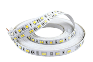
| Compact & Flexible Design | Enables slim, curved, or custom-shaped lighting (e.g., led strip pcb board for automotive interiors). | Supports custom sizes (6mm×6mm to 600mm×700mm) and rigid-flex designs for irregular surfaces |
| Superior Light Quality | Delivers flicker-free illumination with tunable color temperatures and consistency. | Offers rgb pcb led and white light solutions; color binning ensures uniform brightness across batches |
| Instant On/Off Operation | No warm-up time—critical for safety applications like traffic lights or emergency lighting. | Circuit designs prevent voltage spikes during power-on, ensuring stable performance |
| Environmental Friendliness | Mercury-free and 80% more energy-efficient than traditional lighting. | Uses RoHS-compliant materials; recyclable aluminum substrates for eco-conscious projects |
Application Scenarios for LED PCBs
- Automotive Lighting: smd led pcb designs for headlights, brake lights, and ambient interior lighting. Our aluminum-based led light pcb board withstands -40°C to +125°C temperatures, meeting IATF 16949 automotive standards.
- Medical Equipment: Ceramic led pcb for surgical lamps, diagnostic monitors, and dental tools. These boards ensure consistent light output and comply with ISO 13485 medical regulations.
- Industrial Lighting: High-power copper base pcb for factory floors, warehouse lights, and solar-powered streetlights. HCJMPCBA’s designs handle 50A+ currents and resist vibration (MIL-STD-883H compliant).
- Consumer Electronics: Flexible led strip pcb board for smart home lights, TV backlighting, and wearable devices. Customizable lengths and color options (warm white to cool white) fit diverse product needs.
- Traffic & Signage: lighting circuit board solutions for traffic signals, airport runway lights, and outdoor billboards. Weather-resistant coatings protect against rain, dust, and UV exposure.
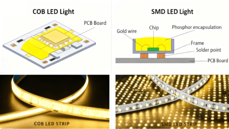
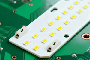
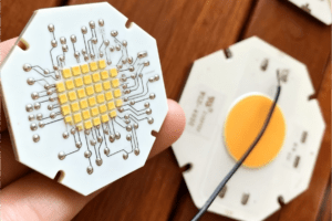
3. SMD LED vs. COB LED: Which Is Right for Your Project?
Two primary LED packaging technologies—SMD (Surface-Mount Device) and COB (Chip-on-Board)—dominate led pcb design. HCJMPCBA supports both, helping you select the optimal option based on your lighting goals, budget, and environment.
| Feature | SMD LED | COB LED |
|---|---|---|
| Packaging Design | Individual LED chips (e.g., 2835, 5050) mounted on smd led pcb via surface-mount tech. | Multiple micro-LED chips directly bonded to the PCB, encapsulated in a single resin layer. |
| Pixel Pitch Range | P10 (10mm) to | P1.5 (1.5mm) to P0.4 (0.4mm)—superior for ultra-high-resolution indoor screens. |
|
| Visual Performance | Bright, vibrant colors with excellent mixing; suitable for dynamic lighting. | Uniform, seamless surface illumination; higher contrast for video walls. |
| Thermal Management | Adequate with proper pcb design for led light (e.g., aluminum substrates). | Better heat dissipation via direct PCB bonding; reduces hotspots. |
| Protection Level | Standard (optional protective masks); vulnerable to dust/moisture. | Fully sealed resin layer; dustproof, moisture-resistant, and impact-resistant. |
| Maintenance | Easy to replace individual LEDs or modules—cost-effective for large installations. | Challenging to repair; better for low-maintenance applications (e.g., high-end retail displays). |
| Cost Efficiency | Scalable pricing; budget-friendly for small to large projects. | Higher upfront cost; premium for high-performance, fine-pitch applications. |
| HCIMPCBA Applications | Automotive lighting, outdoor signage, LED strips. | Medical examination lights, indoor video walls, touchscreen displays. |
HCJMPCBA Tip: For most commercial lighting (e.g., office lamps, streetlights), SMD LEDs on aluminum led pcb offer the best balance of cost and performance. For applications requiring uniform light or harsh conditions, COB LEDs are the preferred choice.
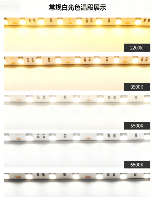
4. Standard White Light Color Temperature Ranges
White led light pcb solutions rely on color temperature (measured in Kelvin, K) to define light “warmth” or “coolness.” HCJMPCBA offers precise color temperature tuning to match your application’s ambiance and functional needs—from cozy residential spaces to clinical medical environments.
| Color Temperature | Light Appearance | Typical Applications | HC.JMPCBA Availability |
|---|---|---|---|
| 2700K | Warm White (yellowish) | Residential bedrooms, hotels, restaurants, mood lighting | Standard; ±200K tolerance |
| 3000K | Soft White | Living rooms, retail stores, cafes, task lighting | Standard; ±200K tolerance |
| 4000K | Neutral White | Offices, schools, commercial kitchens, garages | Standard; ±200K tolerance |
| 5000K | Cool White | Hospitals, workshops, laboratories, parking lots | Standard; ±200K tolerance |
| 6500K | Daylight White (bluish) | Outdoor lighting, security lights, display cases, greenhouses | Standard; ±200K tolerance |
For projects requiring color versatility (e.g., architectural lighting, smart bulbs), HCJMPCBA offers rgb pcb led solutions with digital control—enabling seamless color temperature adjustments and dynamic color effects.
5. Types of LED PCBs
The right led pcb type depends on your project’s thermal requirements, form factor, and budget. HCJMPCBA manufactures six primary types of led light pcb board, each engineered for specific use cases.
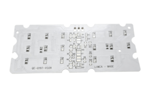
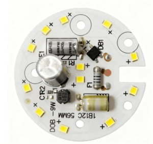
5.1 Aluminum LED PCB (MCPCB)
- Key Features: Metal Core PCB (MCPCB) with a thin, thermally conductive dielectric layer between the aluminum base and copper traces.
- Thermal Conductivity: 1–8 W/mK (varies by dielectric material).
- Advantages: Excellent heat dissipation for high-power LEDs; lightweight and cost-effective vs. copper-based alternatives.
- Applications: Automotive headlights, floodlights, high-bay industrial lamps, and LED grow lights.
- HCJMPCBA Specifications: 0.8–3.2mm total thickness; 1–4oz copper weight; RoHS-compliant; optional thermal interface material (TIM) for enhanced heat transfer.
5.2 FR4 LED PCB
- Key Features: Fiberglass-epoxy substrate (FR4) — the most common PCB material for low-to-medium power LEDs.
- Thermal Conductivity: 0.3 W/mK (lower than metal substrates, suitable for low-heat applications).
- Advantages: Cost-effective; easy to manufacture; flame-retardant (UL94 V-0); compatible with standard PCB assembly processes.
- Applications: Indoor LED panels, decorative lighting, LED indicators, and low-power led strip pcb board (e.g., holiday lights).
- HCJMPCBA Specifications: 0.6–2.4mm thickness; 0.5–2oz copper; available in single/double/multi-layer designs; halogen-free options.
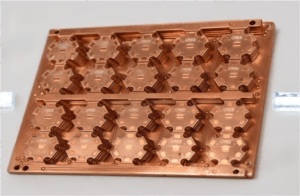
5.3 Copper-Base LED PCB
- Key Features: Thick copper substrate (pure or alloyed) for ultra-high heat dissipation.
- Thermal Conductivity: 385–398 W/mK (far superior to aluminum or FR4).
- Advantages: Handles extreme power loads (100W+ LEDs); minimal temperature rise; ideal for harsh environments.
- Applications: Ultra-high-power industrial lamps, laser diodes, and aerospace lighting systems.
- HCJMPCBA Specifications: 1–5mm copper thickness; 2–6oz top/bottom copper traces; high-current design support (50A+); corrosion-resistant coatings.
5.4 Ceramic LED PCB
- Key Features: Alumina (Al₂O₃) or aluminum nitride (AlN) substrate—offers excellent insulation and thermal performance.
- Thermal Conductivity: 15–200 W/mK (AlN > Al₂O₃).
- Advantages: High-temperature resistance (up to 300°C); chemical stability; low thermal expansion (matches LED chip materials).
- Applications: Medical devices (e.g., surgical lamps), aerospace lighting, and high-reliability industrial LEDs.
- HCJMPCBA Specifications: 0.3–1.5mm thickness; laser-drilled microvias; ISO 13485-compliant for medical projects; hermetic sealing options.
5.5 Flexible LED PCB
- Key Features: Polyimide or polyester substrate—bends and conforms to curved surfaces.
- Thermal Conductivity: 0.15–0.3 W/mK (lower than rigid substrates; best for low-to-medium power LEDs).
- Advantages: Thin (0.1–0.3mm), lightweight; supports custom shapes (e.g., circular, irregular); ideal for space-constrained designs.
- Applications: Led strip pcb board (wearable devices), automotive interior lighting (e.g., dashboard accents), and curved TV backlighting.
- HCJMPCBA Specifications: Rigid-flex hybrid options available; 0.5–2oz copper; IP65/IP67 waterproofing for outdoor use; foldable up to 10,000 cycles.
5.6 Hybrid LED PCB
- Key Features: Combines two or more materials (e.g., FR4 + aluminum, rigid + flexible) to balance thermal performance, cost, and form factor.
- Thermal Conductivity: 0.3–8 W/mK (varies by material mix).
- Advantages: Customizable to project needs—e.g., aluminum sections for high-power LEDs and FR4 sections for control circuits.
- Applications: Complex lighting systems (e.g., smart TVs with backlighting + control boards), multi-functional automotive lighting, and custom led pcb projects.
- HCJMPCBA Specifications: Tailored stackups; mix of rigid/flexible sections; integrated heat sinks; compatible with SMD/COB LEDs.
Comparison Table: LED PCB Types
| Type of LED PCB | Thermal Conductivity | Key Advantages | Typical Applications | HC.JMPCBA Thickness Range |
|---|---|---|---|---|
| Aluminum LED PCB | 1–8 W/mK | Excellent heat dissipation, cost-effective | Headlights, floodlights | 0.8–3.2mm |
| FR4 LED PCB | 0.3 W/mK | Low cost, flame-retardant | Indoor panels, decorative lights | 0.6–2.4mm |
| Copper-Base LED PCB | 385–398 W/mK | Ultra-high power handling, minimal heat rise | Industrial high-power lamps | 1–5mm |
| Ceramic LED PCB | 15–200 W/mK | High temp resistance, chemical stability | Medical devices, aerospace lighting | 0.3–1.5mm |
| Flexible LED PCB | 0.15–0.3 W/mK | Bendable, lightweight, custom shapes | Wearables, curved TV backlighting | 0.1–0.3mm |
| Hybrid LED PCB | 0.3–8 W/mK | Customizable, balances performance/cost | Smart TVs, complex automotive lighting | Tailored to design |
6. Challenges & Considerations in LED PCB Design
6.1 Key Design Challenges & HCJMPCBA’s Solutions
| Challenge | Impact | HCJMPCBA Solution |
|---|---|---|
| Inadequate Thermal Management | Every 10°C temperature rise reduces LED lifespan by 50%; causes color shifting. | – Integrate thermal vias (0.3mm drill) in arrays under high-power LEDs. – Recommend aluminum/copper substrates for 10W+ LEDs. – Simulate thermal flow via ANSYS Icepak to identify hotspots. |
| Color Inconsistency | Mismatched LED colors ruin visual uniformity (e.g., retail displays, office lighting). | – Bin LEDs by color temperature and brightness before assembly. – Use rgb pcb led with digital control for tunable white light. – Conduct 100% visual inspection post-assembly to ensure consistency. |
| Current Overdriving | Excess current (even 10% above rating) damages LEDs and shortens lifespan. | – Design current-limiting resistors and voltage regulators into the lighting circuit board. – Add reverse-polarity protection to prevent damage from incorrect wiring. – Test each board for current stability (±5% tolerance). |
| EMI/EMC Interference | Electromagnetic interference disrupts sensitive devices (e.g., medical monitors, automotive ECUs). | – Add dedicated ground planes and EMI shields to led pcb board designs. – Route high-speed control signals away from LED power traces. – Test for compliance with FCC Part 15 (consumer) and CISPR 25 (automotive) standards. |
| Poor Mechanical Durability | Flexing, vibration, or temperature cycles cause trace cracking or delamination. | – Use flexible polyimide substrates for bendable applications. – Reinforce solder joints with conformal coating for vibration-prone environments. – Conduct thermal cycling tests (-40°C to +125°C) to validate durability. |
6.2 Critical Design Considerations
- Layer Count: Single-layer for simple led strip pcb board; double-layer for medium-power lighting; multi-layer (4–8 layers) for complex designs with control circuits (e.g., dimming, RGB).
- Trace Width: Use 0.2mm (8mil) traces for 1A current; increase to 0.5mm (20mil) for 3A+ to minimize voltage drop.
- Component Placement: Space high-power LEDs 5mm+ apart to avoid overlapping heat zones; place control ICs (e.g., dimming chips) away from hotspots.
- Solder Mask: Choose high-temperature solder mask (Tg ≥150°C) for LED PCBs—prevents melting during reflow soldering (250°C+).
7. Manufacturing Steps for LED PCBs
7.1 Design Validation & DFM Review
- Schematic Review: Our engineers verify your pcb led design schematic (current ratings, LED placement, thermal features) to ensure alignment with project goals.
- DFM Analysis: We check for manufacturability issues—e.g., trace width/space violations, via placement, and substrate compatibility—providing detailed feedback within 24 hours.
- Prototype Planning: For complex projects, we create a prototype blueprint to validate thermal and electrical performance before mass production.
7.2 Material Sourcing & Preparation
- Substrate Selection: Cut aluminum/FR4/ceramic/flexible substrates to size (tolerance ±0.1mm) and clean to remove dust/oil.
- Copper Cladding: Laminate copper foil (0.5oz–4oz) to substrate surfaces using heat and pressure—critical for led pcb board conductivity.
- Prepreg Handling: For multi-layer designs, cut and pre-treat prepreg (resin-impregnated fiberglass) to ensure proper lamination.
7.3 Inner Layer Fabrication (for Multi-Layer PCBs)
- Photoresist Application: Coat inner layers with photosensitive resist to transfer trace patterns.
- Exposure & Development: Expose the resist to UV light through a stencil (with your design pattern); develop to remove unexposed resist.
- Etching: Use chemical etchant (e.g., ferric chloride) to remove excess copper, leaving only the desired traces.
- AOI Inspection: Use Automated Optical Inspection to detect defects (e.g., missing traces, short circuits) with 99.9% accuracy.
7.4 Lamination (for Multi-Layer PCBs)
- Stackup Assembly: Align inner layers, prepreg, and outer copper-clad substrates using laser alignment tools (±25μm accuracy).
- Pressing: Apply heat (180–200°C) and pressure (250–400 psi) to bond the stack into a single rigid board—critical for led pcb structural integrity.
- Cooling: Allow the laminated board to cool to room temperature to prevent warping.
7.5 Drilling & Plating
- Drilling: Use CNC drills (for through-holes) or lasers (for microvias/blind vias) to create holes for component leads and layer connectivity.
- Desmearing: Remove resin residue from drilled holes to ensure proper plating adhesion.
- Electroplating: Plate holes with 20–30μm copper to establish electrical connectivity between layers—HCJMPCBA uses acid copper plating for uniform thickness.
7.6 Outer Layer Fabrication & Finishing
- Outer Layer Patterning: Repeat photoresist application, exposure, and etching for outer copper layers.
- Solder Mask Application: Screen-print or spray LPI solder mask onto the board; cure with UV light to form a protective coating.
- Silkscreen Printing: Apply high-contrast ink (white/black) to label components (e.g., “LED1,” “R1”)—critical for assembly.
- Surface Finish: Apply ENIG (Electroless Nickel Immersion Gold), HASL (Hot Air Solder Leveling), or immersion silver to copper pads—prevents oxidation and ensures reliable soldering.
7.7 Testing & Quality Control
- Electrical Testing: Use flying probe testers to check for shorts, opens, and current stability—100% of boards are tested.
- Thermal Testing: Subject boards to temperature cycling (-40°C to +125°C) and thermal imaging to validate heat dissipation.
- Visual Inspection: Conduct a final check for defects (e.g., solder mask bubbles, silkscreen smudges) against IPC-A-600 Class 3 standards.
- Packaging: Package boards in anti-static bags or custom trays to prevent damage during shipping—HCJMPCBA offers vacuum-sealing for long-distance transport.
8. Why Choose HCJMPCBA as Your LED PCB Supplier?
8.1 Deep Expertise in LED PCB Design
8.2 Strict Quality Control
- Incoming material inspection (substrate, copper, solder mask).
- X-ray inspection for via connectivity (critical for multi-layer led pcb).
- Thermal cycling and humidity testing (IPC-TM-650 standards).
- Final electrical testing (100% open/short verification).
8.3 Full Customization Capabilities
- Support for all substrate types (aluminum, FR4, ceramic, flexible, hybrid).
- Custom shapes/sizes (from 6mm×6mm to 600mm×700mm) and hole patterns.
- Special finishes (ENIG, HASL, immersion silver) and solder mask colors (green/white/black/blue).
- Rgb pcb led designs with digital control (DMX, PWM) for dynamic lighting.
8.4 Competitive Pricing & Fast Lead Times
- Cost Optimization: We reduce costs by 15–30% via panelization (maximizing board count per panel), material selection (e.g., FR4 for low-power designs), and volume discounts (10–20% off for 1000+ units).
- Expedited Services: 3–5 day turnaround for prototypes; 7–10 days for mass production—faster than industry averages (10–14 days).
- Transparent Pricing: No hidden fees—quotes include material, fabrication, testing, and packaging costs.
8.5 Global Compliance & Reach
- International Standards: Our led pcb solutions meet RoHS, ISO 9001 (quality), ISO 13485 (medical), and IATF 16949 (automotive) standards—ensuring compatibility with global markets.
- Global Shipping: We serve clients in 50+ countries, with efficient logistics partners (DHL, FedEx) and customs support to minimize delays.
- Multilingual Support: Our team provides technical assistance in English, Spanish, and Mandarin—critical for international projects.
8.6 End-to-End Support
- Pre-Production: Free DFM reviews and thermal simulation to optimize your led pcb design.
- Production: Real-time order tracking via our online portal—you’ll know the status of your boards 24/7.
- Post-Production: After-sales support (technical troubleshooting, rework if needed) and warranty coverage (1 year for manufacturing defects).
- Long-Term Partnerships: Dedicated account managers for repeat clients—we learn your needs to streamline future projects.