1. Fundamental Principles of Parallel Circuit
Voltage in Parallel Circuit
In any parallel circuit, the voltage across each branch equals the supply voltage. For example, if a 12 V supply is connected to three resistors in parallel, each resistor sees the full 12 V. This characteristic makes parallel circuits ideal in PCB/PCBA scenarios where consistent voltage across multiple components is necessary.
Current in Parallel Circuit
The total current in a parallel circuit is the sum of the current in each branch. Each branch current is given by Ohm’s law: I_branch = V / R_branch. Branches with lower resistance draw more current. Knowing how to calculate current in a parallel circuit helps in trace sizing, thermal design, and load balancing.
Total Resistance in Parallel Circuit
The total or equivalent resistance in a parallel circuit is always less than the smallest individual branch resistance. Use the parallel circuit formula:
1 / R_total = 1 / R₁ + 1 / R₂ + … + 1 / Rₙ
For two resistors: R_total = (R₁ × R₂) / (R₁ + R₂)
Parallel Circuit Diagram
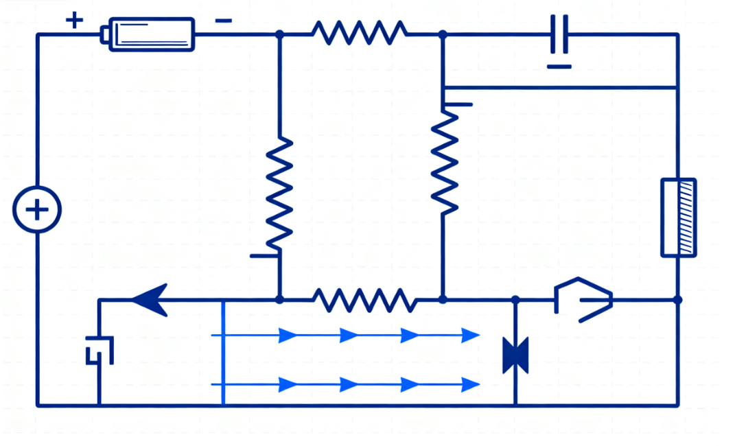
Diagram: resistors in a parallel circuit, each branch connected across the same voltage supply
2. Step-by-Step: How to Calculate Resistance in a Parallel Circuit
- List each branch resistance
R₁, R₂, …, Rₙ. - Compute the reciprocal sum:
1 / R₁ + 1 / R₂ + … + 1 / Rₙ. - Take the reciprocal of that sum to find R_total.
- If the supply voltage
Vis known, compute total current:I_total = V / R_total. - Compute each branch’s current:
I_i = V / R_i.
3. Parallel Circuit Examples
Example 1 – Two Resistors in Parallel
Let R₁ = 100 Ω, R₂ = 200 Ω; supply voltage V = 12 V.
Then:
1 / R_total = 1/100 + 1/200 = 0.01 + 0.005 = 0.015R_total = 66.67 ΩI_total = 12 V / 66.67 Ω ≈ 0.18 A- Branch currents:
I₁ = 12 V / 100 Ω = 0.12 A,I₂ = 12 V / 200 Ω = 0.06 A
Example 2 – Three Resistors in Parallel
Let R₁ = 100 Ω, R₂ = 150 Ω, R₃ = 300 Ω; supply voltage V = 9 V.
1 / R_total = 1/100 + 1/150 + 1/300 = 0.01 + 0.006667 + 0.003333 = 0.020R_total ≈ 50 ΩI_total = 9 V / 50 Ω = 0.18 A- Branch currents:
I₁ = 9/100 = 0.09 A,I₂ = 9/150 = 0.06 A,I₃ = 9/300 = 0.03 A
4. Series vs Parallel Circuits: When to Use Which
| Feature | Series Circuit | Parallel Circuit |
|---|---|---|
| Voltage across components | Divided among components | Same for each branch |
| Current through components | Same through all | Different currents in each branch |
| Total Resistance | Sum of resistances | Less than the smallest branch resistance |
| Failure behavior | If one component fails, series breaks | If one branch fails, others still work |
5. Practical Considerations in PCB / PCBA Design
- Routing & Trace Width: ensure branches with higher current have wider traces; shared nodes must handle combined current.
- Component Tolerances: resistor tolerances (1 %, 0.1 %) impact current distribution in parallel circuits.
- Heat Dissipation: larger currents in branches generate heat; use thermal vias, copper pours, heatsinks.
- EMI / Noise: ground plane layout, shielding, symmetric routing to reduce interference.
- Safety & Protection: fuse protection, proper spacing, isolate potential short branches in design.
6. FAQ
Q1: What is the parallel circuit formula?
The formula for total resistance in a parallel circuit is: 1 / R_total = 1 / R₁ + 1 / R₂ + … + 1 / Rₙ. For two resistors: R_total = (R₁ × R₂) / (R₁ + R₂).
Q2: How do you find current in a parallel circuit?
First compute R_total, then I_total = V / R_total. Each branch current is I_branch = V / R_branch.
Q3: Can voltage drop occur in a parallel circuit?
In idealized circuits, all branches share the same voltage. In real PCB/PCBA designs, trace resistance or connection losses may introduce slight voltage drops.
Q4: What if one branch fails?
If a branch opens (fails), it stops conducting; other branches still function normally. Total current drops; total resistance increases accordingly.
Q5: How to calculate resistance in circuits with both series and parallel parts?
Break down the circuit: calculate equivalent resistance of each parallel group, then combine with series parts using standard formulae for series-parallel circuits.
Summary & Call to Action
For more information about PCBA services, please contact Guangzhou Huachuang Precision Technology.