7 Proven Tips for Choosing the Best Automotive PCB Fabrication & Assembly Partner
Discover the 7 powerful strategies to evaluate and select the best Automotive PCB Fabrication & Asse
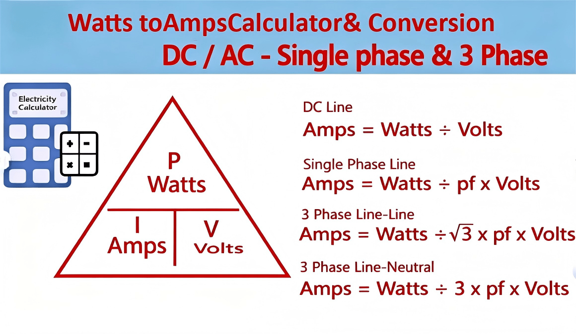
To convert power into current, the basic relationship is that amps = watts ÷ volts (i.e. I=WVI = \tfrac{W}{V}). That means if you know the power in watts and the voltage in volts, you can determine how many amperes (“amps”) flow. In real-world applications—especially in PCB / PCBA design for industrial electronics or OEM devices—you often must account for power factor (PF) in AC systems, or additional safety margins, trace widths, and load variation. This article explains watts to amps conversion (and related calculators / formulas) in DC, single-phase AC, and three-phase systems, with worked examples and tips relevant to power electronics and PCB design.
In the following sections we will cover:
the definitions of watts, amps, volts;
core formulas for converting watts to amperage;
worked examples in different circuit types;
practical pitfalls when applying in PCB / PCBA systems;
recommended online watts to amp converters;
and an FAQ section addressing common “how to convert watts to amps” questions.
Throughout, I’ll bold watts to amps (the main keyword) at least twice, and weave in relevant long-tail keywords (such as watt to amp, w to a, watts amperage calculator, convert watts to amps, watts into amps converter, etc.) for SEO optimization.
When designing PCBs or PCBA assemblies, power delivery is a key concern. Whether you are engineering a motor drive board, an LED lighting module, or a control electronics board, you need to ensure your traces, copper layers, connectors, and power rails can handle the required current without overheating or voltage drop. Knowing how to convert watts to amps is foundational:
It helps you size trace width / copper thickness on the board.
It guides selection of connectors, vias, fuses, and thermal design.
It enables you to check whether a given power budget (in watts) is feasible given your voltage rails.
It is critical when quoting or specifying power modules, power supplies, and when collaborating with procurement or OEM engineers who may specify power (watts) but expect current (amps).
A watts to amp converter in spreadsheet or web form often becomes part of the engineer’s toolkit, but understanding the underlying formula ensures you correctly interpret results and adjust for real-world factors (like power factor, derating, safety margin). That’s why mastering the watts into amps conversion is essential.
A watt (symbol: W) is a unit of power, equal to one joule per second. In electrical circuits, it represents the rate at which electrical energy is consumed or produced. In the relation P=I×VP = I \times V, watts quantify how much energy per unit time flows through a circuit.
An ampere (symbol: A), often shortened to “amp,” is the unit of electric current. It measures the rate of flow of electric charge—how many coulombs of charge pass through a point in the circuit per second. In practical terms, amps tell you how much current a wire or trace must carry.
Voltage (symbol: V) is the electrical potential difference (or “pressure”) that causes current (amps) to flow. If you imagine an analogy: voltage is like water pressure in a pipe; current (amps) is like the amount of water flowing; power (watts) is like the energy delivered by the flowing water.
So the three are related by W = V × I (for resistive circuits and simplified cases) — and rearranging gives I = W ÷ V, the basis for watts to amps conversion under known voltage.
When dealing with AC circuits, you often talk about RMS (root mean square) voltage and power factor (PF), which modifies the simple relationship.
Below are the key formulas used in converting watts to amps under different circuit types. In each case, the relation between power (watts), voltage (volts), and current (amps) is central.
For a DC circuit (constant voltage, no AC waveform complexity):
I=WV\boxed{ I = \frac{W}{V} }
That is, current II in amperes = power WW in watts divided by voltage VV in volts.
E.g. if you have 60 W at 12 V DC, I=60/12=5 AI = 60 / 12 = 5 \, \text{A}.
This is the cleanest watts to amps conversion formula, and is often used in battery, solar, or DC power systems.
For single-phase AC circuits (e.g. typical household or industrial single-phase supply), you must include power factor (PF) because the current and voltage may be out of phase:
I=WV×PFI = \frac{W}{V \times PF}
Here, WW is real power (watts), VV is RMS voltage, and PFPF is the power factor (range 0 to 1).
If the load is purely resistive, PF = 1, and the formula reduces to I=WVI = \tfrac{W}{V}.
In many industrial loads (motors, inductive loads), PF might be 0.8, 0.9, etc.
Some references (e.g. RapidTables) provide that formula for AC:
I(A)=P(W)V×PFI_{(A)} = \frac{P_{(W)}}{V \times PF} rapidtables.com
For three-phase AC systems, the formula depends on whether you use line-to-line (L–L) or line-to-neutral (L–N) voltage. The common formula (line-to-line) is:
I=W3×VLL×PFI = \frac{W}{\sqrt{3} \times V_{LL} \times PF}
VLLV_{LL} = line-to-line RMS voltage
3≈1.732\sqrt{3} \approx 1.732
PF = power factor
This gives the current per phase.
If using line-to-neutral voltage:
I=W3×VLN×PFI = \frac{W}{3 \times V_{LN} \times PF}
Be careful: these formulas assume the load is balanced across all three phases.
RapidTables also outlines these formulas under their Watts to Amps Calculator documentation.
To make things concrete, below are worked examples in DC, single-phase AC, and three-phase AC cases—useful for engineering and PCB / PCBA power design.
Given: 120 W system, powered at 24 V DC
Calculate: Current (amps)
I=12024=5 AI = \frac{120}{24} = 5 \text{ A}
So a 120-watt load at 24 V DC draws 5 amps.
You may also see this expressed in a “watts amperage calculator” tool.
Given: 2000 W load, voltage 230 V RMS, PF = 0.9
Calculate: Current (amps)
I=2000230×0.9=2000207≈9.66 AI = \frac{2000}{230 \times 0.9} = \frac{2000}{207} \approx 9.66 \text{ A}
So a 2000-watt single-phase AC load draws about 9.66 amps (given PF = 0.9).
If PF = 1, then it would be 2000/230=8.70 A2000 / 230 = 8.70 \, \text{A}.
Given: 5000 W load, 400 V line-to-line, PF = 0.85
Calculate: Current per phase
I=50003×400×0.85=50001.732×400×0.85≈5000588.9≈8.49 AI = \frac{5000}{\sqrt{3} \times 400 \times 0.85} = \frac{5000}{1.732 \times 400 \times 0.85} \approx \frac{5000}{588.9} \approx 8.49 \text{ A}
Thus each leg carries ~8.49 A.
Note: If you have line-to-neutral voltage VLN=230 VV_{LN} = 230 \, \text{V} (for example), you’d apply the alternate formula accordingly.
These examples illustrate how to use the watts to amp conversion formula in real engineering design contexts.
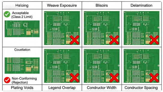
When applying watts to amps conversions in a PCB / PCBA design, several practical considerations can complicate the ideal formulas above. Below are key pitfalls and tips to watch out for.
In AC circuits, assuming PF = 1 is tempting but often inaccurate for reactive loads (motors, inductors, switching supplies). Underestimating the impact of PF can lead to under-design of currents or thermal stress.
Even if your converted current is correct, voltage drop across PCB traces or vias can reduce useful voltage at load. Use copper trace width calculators and derating tables to allocate margin. Account for IR drops (I×R)(I \times R) in your design.
In PCB / PCBA power systems, you should include safety margin (e.g. +20–30%) over the theoretical current to allow for manufacturing variance, temperature rise, and aging.
Many boards see dynamic current draw (e.g. peak loads, inrush). The steady-state amps from watts conversion must be augmented with peak current considerations. Use the watts into amps converter only as a baseline.
If the load across the three phases is not balanced, current may exceed predictions on certain phases. Always review phase balancing.
In power modules or switching supplies, losses (e.g. heat, conversion inefficiencies) mean the real input current is higher than theoretical. Factor in efficiency (e.g. 90%, 95%) when converting.
Regulations (UL, CE, IPC, etc.) often require margin for surge, EMI filtering, and derating. These overheads mean you should oversize current capacity beyond pure conversion.
In summary: the formula-based conversion is a starting point—but good engineering design always layers in margins, real-world derating, and robust verification.
Here are some useful online watts to amp converter / wattage to amperage calculator tools you can use to validate your manual calculations:
RapidTables – Watts to Amps Calculator: supports DC, AC single-phase, 3-phase formulas.
OmniCalculator – Wattage to Amperage: lets you input PF, voltage, circuit type, etc.
InchCalculator – Watts to Amps Conversion: includes calculators and worked tables.
ElectricalSafetyFirst – Watts to Amps: general reference for basic formula and safety context.
When using these tools, you should check the default assumptions (e.g. PF = 1) and adjust for your real system. You can build your own watts to amp calculator in spreadsheets as part of your design toolkit, so you can iterate quickly.
Tip: embed a light watts to amps converter on your company website or blog, so OEM engineers or purchasers can quickly check current requirements—this also helps attract organic traffic for long-tail keywords like amp calculator from watts, watts converter to amps, convert watts to amps, etc.
Below are some Frequently Asked Questions (QFA) around watts to amps conversions, phrased in common user queries.
Q: Can you convert watts to amps without knowing voltage?
A: No — watts measure power and amps measure current, but to convert one to the other you must know the voltage. In formulas like I=WVI = \tfrac{W}{V} or I=WV×PFI = \tfrac{W}{V \times PF}, voltage is essential.
Q: Why does power factor matter in AC “watts to amps” calculation?
A: In AC circuits, real power (watts) differs from apparent power (volt-amperes) if current and voltage are out of phase. Power factor PF=real powerapparent powerPF = \tfrac{\text{real power}}{\text{apparent power}} adjusts the simple formula so that I=WV⋅PFI = \tfrac{W}{V \cdot PF} gives correct current for loads with reactive components.
Q: How many amps are in 1 watt at 120 V or 230 V?
A: At 120 V DC or AC (assuming PF = 1), 1 W=1120 A=0.00833 A1 \, \text{W} = \tfrac{1}{120} \, \text{A} = 0.00833 \, \text{A}. At 230 V, 1 W=1230=0.00435 A1 \, \text{W} = \tfrac{1}{230} = 0.00435 \, \text{A}. Real systems will vary if PF < 1.
Q: Does this “watts to amp converter” formula apply to non-resistive loads (motors, capacitances)?
A: The formulas still apply to compute real current, but reactive / non-resistive loads require adjustments for PF, harmonics, or non-linear behavior. Always check manufacturer specs and derate accordingly.
Q: How do I convert from watts to amps in three-phase systems?
A: Use I=W3⋅VLL⋅PFI = \tfrac{W}{\sqrt{3} \cdot V_{LL} \cdot PF} for line-to-line systems, or the alternative formula using line-to-neutral voltage for balanced loads. The concept remains the same: divide power by voltage × geometry factors × PF.
Q: How do you calculate watts to amps for pulsed or dynamic loads?
A: You must consider peak current, duty cycle, RMS current, and possibly transient surges. Use the steady-state watts to amps result as a baseline, then overlay the additional peak/dynamic margin in your design.
The fundamental formula is I=WV\boxed{I = \tfrac{W}{V}} (amps = watts ÷ volts). For AC systems, include the power factor: I=WV×PFI = \tfrac{W}{V \times PF}. For three-phase systems, include 3\sqrt{3} factors.
In PCB / PCBA design, power-to-current conversion is a key starting point, but must be tempered with derating, trace losses, thermal margin, converter inefficiencies, and dynamic loads.
Use trustworthy watts to amps converter tools (e.g. RapidTables, OmniCalculator) to check your calculations, but always validate against your real system conditions.
Include safety margin, consider PF, account for thermal / aging derating, and always validate currents via praktical testing or worst-case load simulations.
Embedding a converter or worked examples on your website helps users and can boost SEO rankings for long-tail keywords like watt to amp formula, amp calculator from watts, convert watts to amps, watts into amps conversion, etc.
By mastering watts to amps conversions and integrating them into your power electronics and PCB / PCBA designs, you can ensure safe, reliable, and efficient systems.
To discover tailored PCBA & PCB manufacturing services with power design support, contact Guangzhou Huachuang Precision Technology (HCJMPCBA).
Discover the 7 powerful strategies to evaluate and select the best Automotive PCB Fabrication & Asse
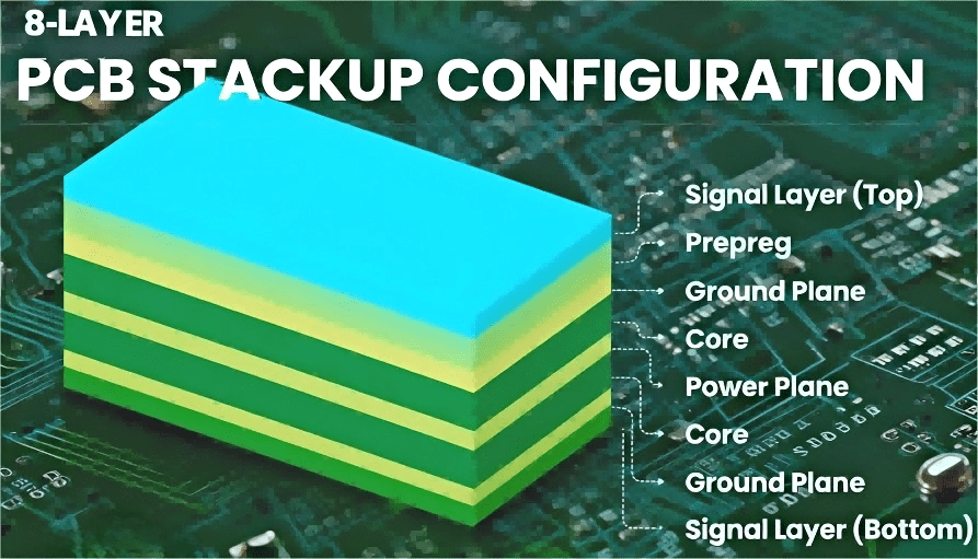
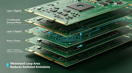
Discover what is an 8 layer pcb stackup, best layer configurations, materials, signal integrity stra
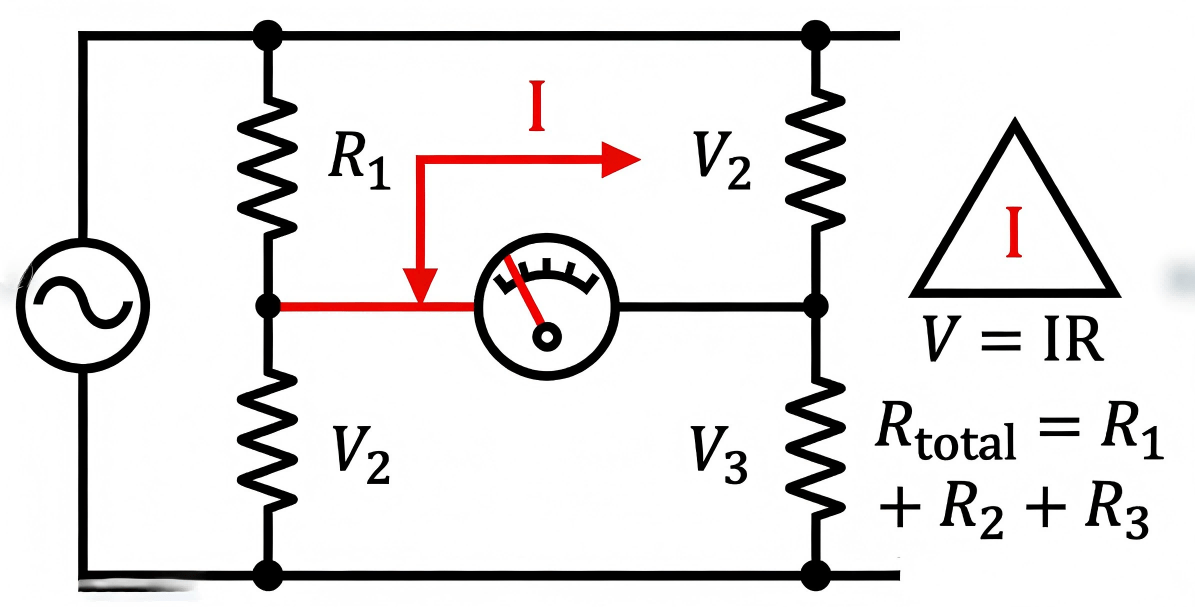
Looking for a definitive guide on what is a series circuit? This engineering deep dive by the HCJMPC