Huachuang PCBA Processing Factory: High – speed Chip Mounters – The Core Driving Force of Electronic Manufacturing
This article focuses on the high - speed chip mounters in Huachuang PCBA Processing Factory. It firs
Surface‐Mount Technology (SMT) has revolutionized electronics manufacturing by enabling higher component density, improved performance, and greater automation.
SMT places discrete components directly onto the surface of a printed circuit board (PCB), as opposed to inserting leads through holes (Through-Hole Technology, THT). Developed in the 1960s and widely adopted in the 1980s, SMT enables:
Miniaturization: Ultra-small parts such as 0201 and 01005 packages
Higher Throughput: Automated lines achieve 50,000 placements per hour
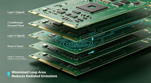
Improved Electrical Performance: Shorter signal paths reduce parasitic effects
Case Study: HCJMPCBA replaced a medical imaging OEM’s legacy THT boards with an SMT PnP process, reducing board size by 30% and doubling production throughput.
Material Receipt & Cleaning
Inspect copper‐clad laminates for flatness and lamination defects
Ultrasonic cleaning to remove oils, dust, and oxides
Copper Clad Quality Tests
Measure foil thickness and adhesion
Verify solder mask adhesion strength
Paste Formulations
Lead-free (SnAgCu) vs. Leaded (SnPb): choose based on RoHS compliance and thermal profile
Rheology must match stencil aperture and board layout
Screen & Stencil Parameters
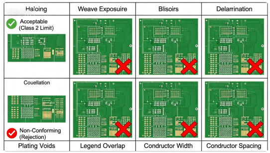
Common Defects & Optimization
Equipment Components
Accuracy & Calibration
Speed vs. Precision
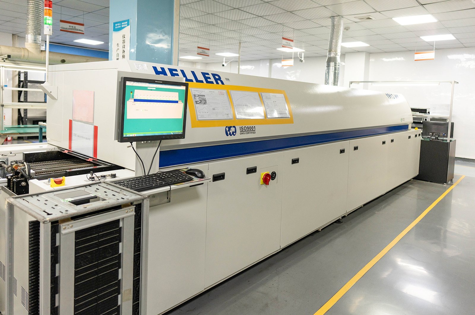
Five-Zone Profile
Thermal Profiling
2.Troubleshooting Defects
Automated Optical Inspection (AOI)
X-Ray for Hidden Joints
Manual Rework
Paste Types: No-clean vs. water-soluble
Flux Roles: oxide removal, wetting enhancement
0201 / 0402: require specialized pick-and-place heads
Package Types: QFP, BGA, CSP; each demands unique reflow and inspection settings
| Finish | Pros | Cons |
|---|---|---|
| HASL | Low cost, robust | Unevenness limits fine pitch |
| ENIG | Flat, reliable | Costly, risk of black pad |
| OSP | Excellent for fine pitch | Limited shelf life |
Cleaning Solutions: DI water, semi-aqueous sprays
Coating Options: acrylic, silicone, urethane for moisture/dust protection
AOI: verifies post-reflow results
Flying Probe: flexible for low-volume runs
ICT (In-Circuit Test): faster for high-volume, once fixtures are built
Thermal Cycling: −40 °C to +125 °C
Vibration & Shock: automotive standards
Solder Bridges: often due to excessive paste—control stencil aperture
Tombstoning: match component geometry and optimize ramp-rates
Component Offset: maintain precise fiducials and routine nozzle cleaning
Yield vs. Throughput: implement statistical process control (SPC) and make real-time adjustments
Consumer Electronics: ultrathin smartphones and wearables demand 01005 support
Automotive Electronics: functional safety (AEC-Q100) boards for ECUs and sensors
Medical & Aerospace: traceability, biocompatible coatings, and stringent reliability
The SMT process is the backbone of modern electronics manufacturing, offering precision, speed, and flexibility. From SMT PnP process and SMT PoP process workflows to rigorous quality controls and materials selection, each stage shapes the reliability and performance of your PCBAs.
If you need to learn more about PCBA design, manufacturing and testing services, please contact Guangzhou Huachuang Precision Technology.
This article focuses on the high - speed chip mounters in Huachuang PCBA Processing Factory. It firs
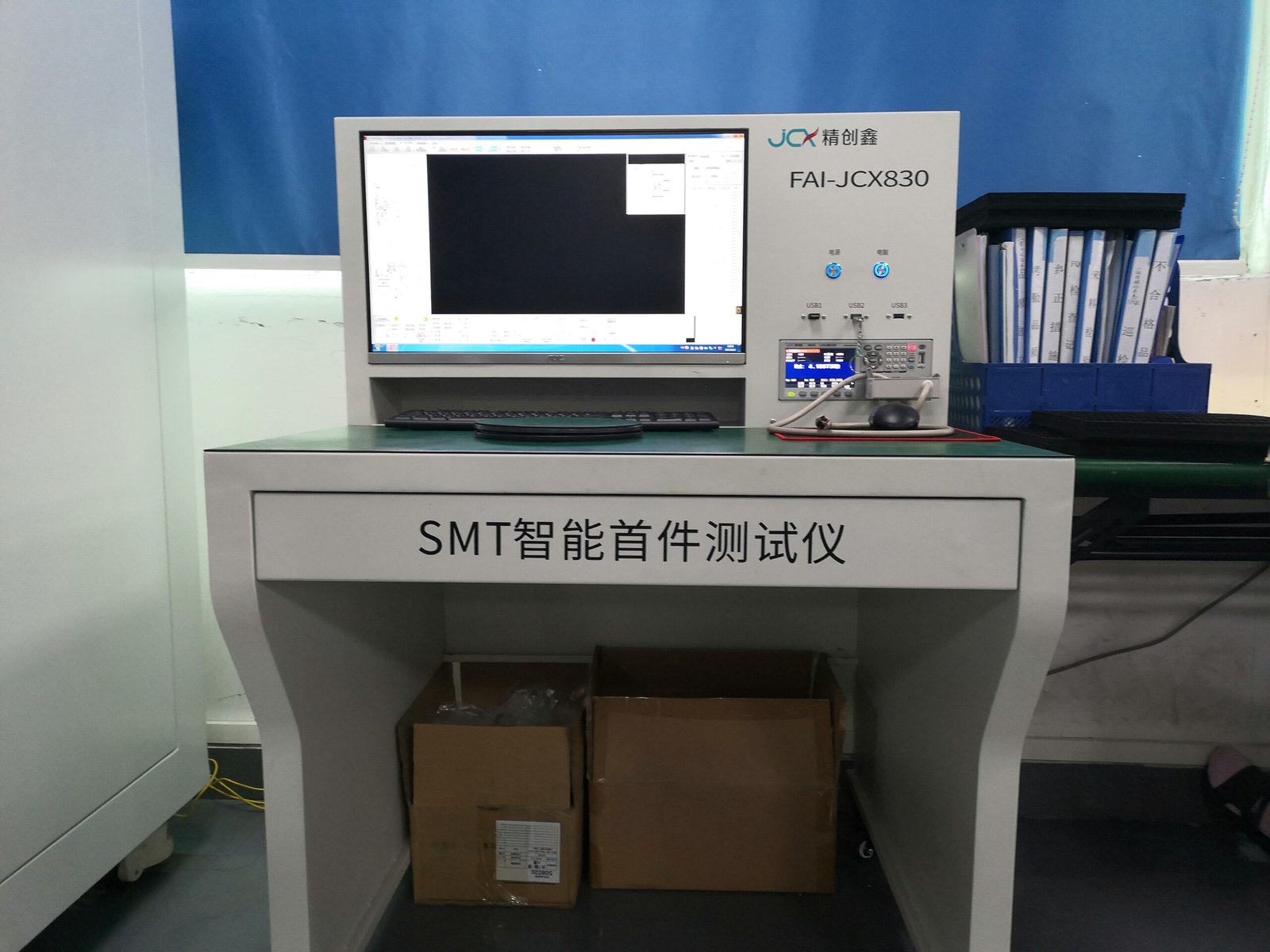
Guangzhou Huachuang Precision Technology Co., Ltd. offers efficient and precise first article inspec
Guangzhou Huachuang Precision Technology Co., Ltd. utilizes advanced wave soldering technology to pr