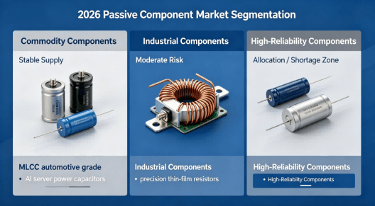
2026 Global Resistor and Capacitor Market Reality: Supply Pressure, Price Volatility, and Engineering-Level Risk Control in PCB & PCBA Manufacturing
Direct Answer The global resistor and capacitor market in 2026 is no longer a stable commodity envir
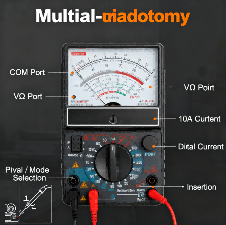
A multimeter is used to measure voltage (V), resistance (Ω), and current (A) in electrical circuits.
To use a multimeter correctly:
1.Select the correct measurement mode (Voltage, Resistance, Continuity, or Current).
2.Insert probes into the proper ports.
3.Place the probes on the circuit test points.
4.Read the measurement result from the display.
These steps allow engineers to safely diagnose electronic circuits, PCB boards, batteries, and power supplies.
Before testing a circuit, choose the correct dial setting:
V⎓ – DC voltage
V~ – AC voltage
Ω – resistance
🔔 (continuity) – short circuit detection
Selecting the wrong mode is the most common mistake when learning how to use a digital multimeter.
When testing electronics such as PCB boards, always connect the black probe to ground (GND) and measure signals using the red probe.
This method is widely used in PCB troubleshooting and manufacturing testing.
Professional technicians follow this sequence:
This prevents accidental short circuits and protects sensitive components during printed circuit board testing.
A digital multimeter (DMM) measures three fundamental electrical parameters.
| Measurement | Symbol | Purpose |
|---|---|---|
| Voltage | V | Measures electrical potential |
| Resistance | Ω | Measures circuit resistance |
| Current | A | Measures electrical flow |
These measurements help engineers diagnose problems in:
power supplies
industrial control boards
consumer electronics
IoT devices
automotive PCBs
In electronics manufacturing, multimeters are often used for initial circuit validation before automated testing systems.
Most multimeters have three ports:
COM – black probe
VΩmA – red probe for voltage/resistance
10A – high current testing
Always connect the black probe to COM first.
Rotate the dial to the correct measurement type.
Typical modes include:
DC voltage
AC voltage
resistance
diode testing
continuity testing
Modern digital multimeters automatically detect ranges, making them easier for beginners.
To measure voltage:
1.Set the multimeter to DC voltage (V⎓).
2.Place the black probe on ground.
3.Touch the red probe to the test point.
Example results:
| Circuit Type | Expected Voltage |
|---|---|
| USB Power | 5V |
| Logic Circuit | 3.3V |
| Automotive Battery | 12V |
Voltage measurement is the most common step when learning how to check a circuit board with a multimeter.
Continuity testing detects short circuits or broken connections.
Steps:
1.Set the dial to continuity mode (beep symbol).
2.Touch probes to both ends of a circuit path.
3.If the meter beeps, the circuit is continuous.
Engineers often use this method for:
PCB trace inspection
cable diagnostics
solder joint verification
Resistance testing helps identify:
damaged resistors
broken traces
incorrect component values
To measure resistance:
1.Set the dial to Ω.
2.Place probes across the component.
3.Read the value displayed.
Important rule:
Never measure resistance while the circuit is powered.
Hcjmpcba Multimeter Anatomy Dial & Ports Layout
In professional electronics manufacturing, multimeters are part of the first-level diagnostic process before automated inspection.
For example, during PCBA prototype validation, engineers typically verify:
| Test Point | Expected Result |
|---|---|
| Power rail | 3.3V / 5V |
| Ground continuity | near 0Ω |
| Diode forward voltage | 0.5–0.7V |
| Capacitor leakage | high resistance |
At HCJMPCBA, multimeter testing is integrated into the early New Product Introduction (NPI) stage before boards move to automated testing systems like ICT and functional testing.
This hybrid approach ensures high reliability for industrial, medical, and AI electronics applications.
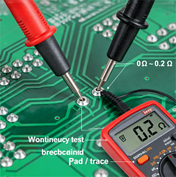
Hcjmpcba Continuity Test On Pcb Pad Trace
Even experienced technicians occasionally make these errors.
This can damage both the multimeter and the PCB.
Oxidized pads may cause unstable readings.
Technicians often lightly scrape the probe tip to ensure proper contact.
Probe wires themselves add 0.2–0.5Ω, which affects low-resistance measurements.
Measuring AC voltage while in DC mode can show incorrect readings.
Professional engineers use several techniques to improve accuracy.
This captures sudden voltage drops during intermittent faults.
Electromagnetic interference can create false readings in high-impedance circuits.
Always confirm ground integrity before measuring signal rails.
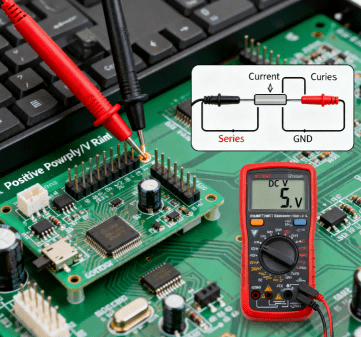
Hcjmpcba Voltage & Current Testing On Assembled Pcb
Q:How do you use a multimeter to test a PCB?
A:Set the meter to continuity or voltage mode and probe the PCB test points to verify connections and power rails.
Q:What is the easiest measurement for beginners?
A:Voltage testing is usually the easiest way to start learning how to use a multimeter.
Q:Can a multimeter detect a short circuit?
A:Yes. Continuity mode will beep when a short circuit exists between two points.
Q:What industries rely heavily on multimeter testing?
A:Multimeters are widely used in:
electronics manufacturing
automotive repair
industrial automation
HVAC control systems
IoT device development
Understanding how to use a multimeter is a fundamental skill in electronics.
From basic voltage checks to advanced PCB diagnostics, multimeters remain one of the most important tools for engineers, technicians, and hardware developers.
In professional electronics manufacturing, they serve as the first diagnostic step before automated testing systems.
Update triggers: standard revision changes / recurring questions / production checklist updates.
If you are developing new electronic products and need reliable PCB assembly or PCBA manufacturing, the engineering team at HCJMPCBA supports global OEM clients with:
prototype PCB assembly
small-batch manufacturing
industrial PCBA production
engineering testing and validation
Direct Answer The global resistor and capacitor market in 2026 is no longer a stable commodity envir
Discover how HCJMPCBA leverages the advanced Samsung SM471 machine to optimize the PCB manufacturing
Introduction Robotics is no longer limited to automotive factories or research laboratories. Today,