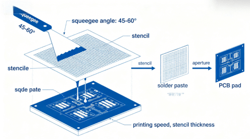
7 Critical Dimensions of Ball Grid Array (BGA) Quality Control: The Definitive Industrial Guide to Zero-Defect PCBA
What is a Ball Grid Array (BGA) and how do you ensure quality control in BGA components? This guide
Surface Mount Device (SMD) packages such as 0805 have become ubiquitous in modern PCB assembly because they balance compact size, power handling, and manufacturability. For OEM engineers, procurement decision-makers, and cross-industry buyers, questions often arise like: What exactly is an SMD 0805 resistor? How much power can an 0805 handle? Can you reliably probe 0805 components during testing without damage?
This comprehensive guide answers those questions and more — it explains what SMD 0805 is, essential parameters such as size and power rating, proven methods for probing these tiny parts, and how HCJMPCBA manages 0805 components throughout PCBA design, test, and production cycle to reduce risk and improve reliability.
Throughout the article, we’ll use structured sections, clear definitions, practical testing techniques, and expert steps to support engineers and buyers in making informed PCBA decisions.
Natural inclusion of keywords like can you probe 0805, 0805 resistor, 0805 resistor dimensions, and probe measurements ensures clarity and SEO value for search intent focused on How-to, Component Specs, and Testing Techniques.
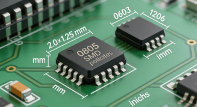
An SMD 0805 refers to a surface mount package with an imperial code of “0805”—roughly 0.08 inches by 0.05 inches (≈ 2.0 mm × 1.25 mm) in length and width. This size strikes a balance between compact layout and practical handling in PCBA manufacturing.
The “0805” code originated from imperial measurements; it is often translated into metric footprint names like 2012 but engineers widely use 0805 as the standard naming convention in both resistor and capacitor catalogs. Unit Circuits
Why 0805 Matters in PCBA:
Larger than ultra-compact formats like 0603 — making manual inspection and rework easier
Smaller than 1206 — saving precious board space
Compatible with automated pick-and-place machines at high throughput
This makes 0805 SMD parts ideal for medium-power signal lines, decoupling functions, and wide applications from IoT modules to industrial controllers.
Within the 0805 footprint, multiple discrete components exist — including:
0805 Resistors & Capacitors used for current limiting, voltage division, and signal conditioning
Cap 0805 ceramics for decoupling and noise suppression
Inductors, diodes, and small network modules that adhere to the same footprint standard
HCJMPCBA maintains a verified component library with 5,000+ 0805 parts ready for use in production, minimizing sourcing delays and strengthening supply reliability.
A typical 0805 resistor measures:
Length: ~2.0 mm
Width: ~1.25 mm
Thickness: Standard small-signal profile
These dimensions enable reliable soldering and testing without compromising board density. Unit Circuits
Power rating is a critical specification that defines how much energy a resistor can safely dissipate. For standard 0805 resistors:
Continuous power rating often lies around 0.125W (1/8W) for general thick-film parts.
Derated ratings (e.g., up to 0.25W) may be specified depending on design and manufacturer.
Some high-power 0805 variants push up toward 0.33W or even 0.5W for specialized thick-film versions, particularly automotive-grade AEC-Q200 resistors.
Note: manufacturers’ datasheets always provide exact values; generic values vary by composition and substrate.
What Does This Mean for PCBA Designers?
Choosing the correct power rating is indispensable, especially where heat buildup may degrade component life or disrupt surrounding components on the board. For robust performance, always pick an 0805 part with a power rating that exceeds the expected load and ensure ambient derating curves are respected.
If an 0805 resistor power rating is undersized for the application, the component may overheat, drift in resistance, or even fail. Accurate sizing prevents:
Thermal stress and board warping
Signal integrity issues due to resistor drift
Overload and cascading component failure
HCJMPCBA’s engineers proactively cross-verify resistor power ratings with schematic requirements during the design phase — helping clients avoid costly rework and burn-in failures in critical applications.
Understanding can you probe 0805 is essential because small SMD components lack traditional test points and are held rigidly by solder. Probing requires deliberate technique and proper tooling to avoid damage.
Because 0805 parts sit flush on the PCB with tiny terminations, the main challenges include:
Tiny footprint makes contact difficult without slipping
Standard hook tips may not grab the component’s terminal
Excessive force during measurement can lift solder joints or distort the part
This is why intentional probe measurements must use suitable tools to guarantee accurate, repeatable results.
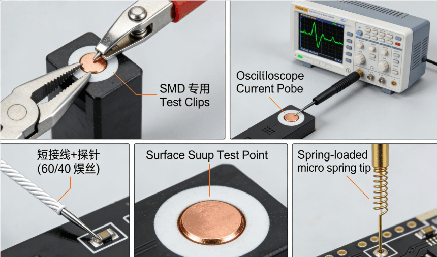
5 Common 0805 Probing Methods Hcjmpcba
0805 Smd Hcjmpcba
Below are practical and reliable ways to perform probe measurements around 0805 SMD parts:
Spring-loaded or micro gripper SMD test clips offer secure contact on an 0805 pad or side termination. These clips help ensure repeatable measurements when capturing the voltage across 0805 components. Specialized spring tips and grippers are available for tight spaces.
For more accurate oscilloscope probing:
🔹 Place a short, heavy-gauge solder on each side of the 0805 component
🔹 Solder a short loop of wire (e.g., Kynar/28AWG) to the soldered ends
🔹 Clip the oscilloscope probe to the wire for a stable measurement
Using 60/40 solder (60% tin, 40% lead) helps because its lower melting point (≈183°C) reduces the risk of thermal damage while forming a reliable pad for test leads.
High-precision micro probes with spring-loaded tips are ideal for small surface mount test points. These may include gold-plated spring needle tips that resist slipping — especially useful in production labs.
During PCB layout stage, add dedicated surface mount test points near critical signals. These test pads (sometimes as small as 0.05 in) provide reliable contact for probes and allow engineers to attach oscilloscope leads without touching the tiny 0805 parts directly.
Where direct contact to resistor terminals is impractical, use current probes to measure signal or current flow. A current probe clamps around a lead or wire to provide measurement without physically touching the component, especially valuable for high-frequency or dynamic current testing. Oscilloscope probe accessories (such as differential or low-capacitance probes) further enhance signal fidelity.
HCJMPCBA follows a structured process for 0805 signal and component testing:
Tool Selection: Choose the appropriate tooling (SMD test clip, spring probe, or current probe).
Secure Setup: Mount PCB on anti-static workbench and use test points for ground reference.
Probe Attachment: Connect the chosen probe to the test fixture or clip.
Record & Validate: Perform measurement with oscilloscope or DMM and compare results with design specs.
Document Results: Log test data and attach to quality reports.
This SOP ensures high-confidence 0805 probing with minimal risk of damage or false readings.
Issue: Clips slip off or cause inconsistent contact
Solution: Use micro spring probes or dedicated SMT test points; secure wires before probing.
Issue: Probe noise distorts waveform
Solution: Use shielded cables, attenuated probes, or differential probes to reduce noise.
Issue: Counterfeit or non-spec’d 0805 parts
Solution: HCJMPCBA sources from authorized distributors (Digi-Key, Mouser) with traceable certifications.
Issue: Poor solder joint formation at high thermal loads
Solution: Use appropriate 60/40 reflow profiles and perform thermal cycling tests to validate assembly integrity.
Expertise in Miniaturized PCBA: 20+ years of experience with high-density designs
Advanced Test Lab: Oscilloscopes, micro probes, and current probe instruments for accurate SMD measurements
Clear Documentation & Traceability: Clients receive detailed reports on probe measurements, solder profiles, and component performance
Understanding **what SMD 0805 is, typical power ratings (like ~0.125W), how to interpret 0805 resistor sizes, and techniques for can you probe 0805 SMD components is essential to success in modern electronics design and manufacturing. With the right test points, clips, probes, and HCJMPCBA’s structured SOPs, engineers and procurement teams can reduce risk, improve quality, and confidently bring products to market.
What is a Ball Grid Array (BGA) and how do you ensure quality control in BGA components? This guide

Automated Optical Inspection (aoi inspection pcb) is a non-contact, high-speed quality control metho
EasyEDA is a powerful, browser-based EDA tool for schematic capture, simulation, and PCB design—co