What Is a Gerber File? — Complete Guide for PCB / PCBA Professionals
Discover what a gerber file is, why it is the universal “language” for PCB manufacturing, how to
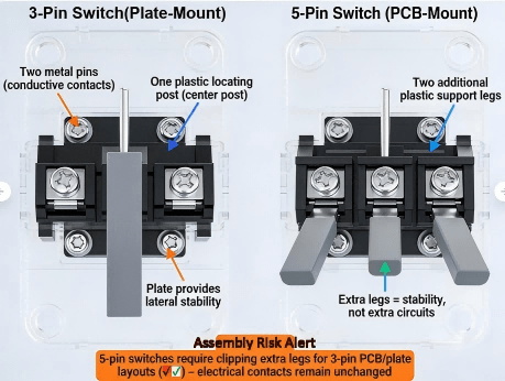
A 3 pin switch (often called “plate-mount”) typically has two metal pins for electrical contact plus one plastic locating post. A 5 pin switch (often called “PCB-mount”) adds two extra plastic support legs to improve stability and reduce wobble. In most keyboard PCBs, 3-pin switches can fit 5-pin footprints, but 5-pin switches may require clipping the two extra plastic legs to fit a 3-pin-only PCB/plate layout. Pin count here is mainly about mechanical mounting, not “more electrical capability.”
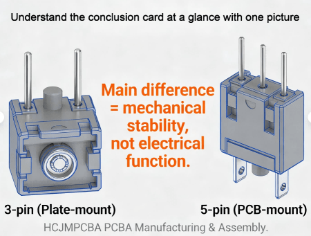
3 Pin Switch And 5 Pin Switch
For Cherry MX-style keyboard switches, “3 pins” usually describes the bottom geometry used to mount the switch into a plate/PCB system:
Two metal pins: the conductive contacts that connect into the PCB (or into a hot-swap socket).
One plastic locating post (center post): helps align the switch and reduce rotation.
Many industry guides group these as plate-mounted because a plate (sheet material) provides most of the lateral stability.
Why it matters for PCBA:
With a 3 pin keyboard switch (sometimes searched as 3 pin keyboard switch or 3 pin key switch), the build quality depends heavily on plate cutout tolerance, plate thickness, and assembly order. If the plate is loose or the cutout is oversized, wobble and uneven feel can show up even when the electrical contact is fine.
A “5-pin” keyboard switch usually means:
The same two metal contact pins + center locating post, plus
Two additional plastic support legs (extra mounting posts)
Those extra posts don’t carry current; they carry mechanical load. They reduce rocking under off-center presses and improve consistency—especially important when you have no plate, a flexible plate, or tighter feel targets.
Plain-language engineering explanation:
Think of switch pins and posts as “legs on a chair.” More support legs can reduce wobble, especially when the PCB is thin, the plate is soft, or the user presses at the edge of the keycap.
3 Pin Switch And 5 Pin Switch Cross Sectional View Comparing Bottom Structures
“Hot-swappable keyboard” usually means the keyboard PCB includes hot-swap sockets, so you can remove and replace switches without soldering. It simplifies maintenance and switch testing across different keyboard switch types.
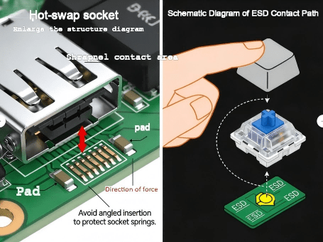
Key point: a socket is on the PCB, not on the switch. The switch’s metal pins insert into the socket’s contacts. That’s why a 5 pin switch keyboard socket discussion often overlaps with manufacturing topics: socket solder strength, pad design, and insertion alignment matter as much as the switch itself.
To make OEM builds stable and scalable, engineers typically choose one of these approaches:
Hot-swap socket (no solder for switches): faster service, less rework risk, but demands robust pad design and controlled insertion angle.
Through-hole soldered switch pins: strong electrical joint but higher rework effort; needs solder process discipline.
Hybrid designs: socket + selective reinforcement or additional mechanical support in high-stress areas.
For reliability programs, it’s also common to align ESD expectations with system-level immunity testing methods like IEC 61000-4-2, because repeated human contact (key presses) can introduce ESD events at the interface.
5 Pin Switch Keyboard Socket
Usually yes. A 5-pin PCB footprint has holes for the two metal pins and the center post, plus holes for the two extra plastic legs. A 3-pin switch simply won’t use those extra holes.
Often not directly. If the PCB/plate layout doesn’t include the extra two holes, the two plastic legs interfere. Many guides recommend clipping the two extra plastic legs so the switch can fit; the electrical pins remain unchanged.
Even if the switch fits, feel and stability depend on plate (sheet material) details—especially in plate-dominant builds. Plate cutout tolerance and thickness can outweigh the pin-count difference. Mechanical Keyboards
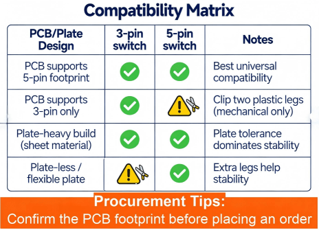
Compatibility Matrix (copy-friendly):
| PCB/Plate Design | 3-pin switch | 5-pin switch | Notes |
|---|---|---|---|
| PCB supports 5-pin footprint | ✅ Fits | ✅ Fits | Best universal compatibility |
| PCB supports 3-pin only | ✅ Fits | ⚠️ Needs clipping | Clip two plastic legs (mechanical only) |
| Plate-heavy build (sheet material) | ✅ Common | ✅ Common | Plate tolerance dominates stability |
| Plate-less / flexible plate | ⚠️ More wobble risk | ✅ Preferred | Extra legs help stability |
Compatibility Matrix Table For 3 Pin And 5 Pin Switches
Before inserting any switch into a socket or PCB:
Check the footprint match: confirm whether the board expects 3-pin or 5-pin.
Inspect switch pins: look for bent metal pins, oxidation, or contamination (switch pins should be straight and clean).
Inspect sockets/pads: hot-swap socket springs should be centered; through-hole pads should be intact.
ESD baseline: for OEM production lines, treat switch insertion as an ESD touchpoint and apply ESD controls aligned with IEC 61000-4-2 thinking (operators, fixtures, grounding).
This applies to hot swappable keyboard designs (hot swappable keyboard meaning: replace switches without solder).
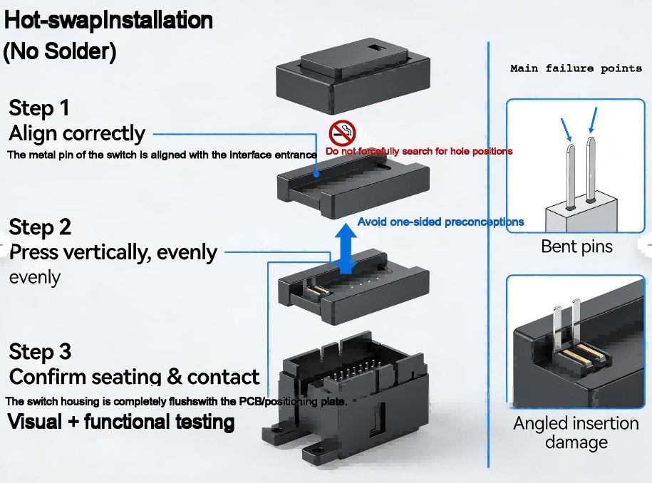
Step 1 — Align correctly
Orient the switch so the two metal pins align with the socket entry.
Do not “search” for the hole with force. Misalignment can deform socket springs.
Step 2 — Press vertically, evenly
Press straight down using uniform pressure.
If one side seats first, remove and retry; angled insertion can cause intermittent contact.
Step 3 — Confirm seating & contact
Visual check: the switch housing should sit flush on the plate/PCB.
Functional check: run a key tester to confirm no chatter, missed inputs, or intermittent contact.
Repeatability tip for OEM:
A simple fixture that ensures vertical insertion angle can dramatically reduce socket damage in production.
If your project uses soldered switch pins (through-hole), the acceptance criteria should be aligned to known workmanship standards.
Step 1 — Stabilize before soldering
Use plate/fixture support to keep the switch perpendicular.
This is where 5-pin vs 3-pin switches can change your yield: the extra legs on a 5-pin switch reduce movement during soldering.
Step 2 — Solder with process discipline
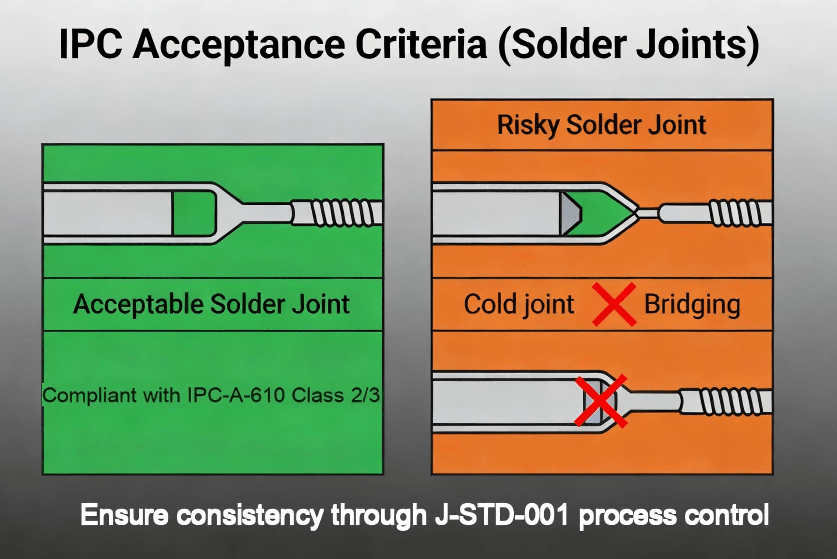
Aim for consistent wetting and fill; avoid cold joints and bridging.
Treat this as a J-STD-001-style process control issue (materials, heat, cleanliness, operator training).
Step 3 — Inspect to IPC acceptance language
IPC-A-610 is widely used for assembly acceptability criteria; buyers often require “IPC Class 2 or Class 3 workmanship” depending on product grade.
Confirm Whether The Board Expects 3 Pin Or 5 Pin
Ipc Acceptance Point Schematic Diagram
In plate-heavy builds, the plate (sheet material) provides most lateral support. If the cutout is loose, a 3 pin switch can wobble even if it’s electrically fine. This is why many guides associate 3-pin with plate-mount use cases.
A stable, repeatable order is:
Stabilizers (if any)
Plate (sheet material)
Switch insertion into plate
PCB alignment & final seating
Socket engagement or soldering
This reduces stress on the PCB and improves consistency across different types of keyboard switches.
A 3 pin keyboard switch can be the right choice when:
The plate is rigid and precisely cut
Serviceability matters (especially with hot-swap)
Cost targets and supply chain availability favor 3-pin variants
Your product spec tolerates slightly higher wobble, or you mitigate it with plate design
Hot-swap speeds service and switch evaluation across keyboard switch types, but socket quality and pad design become critical.
Through-hole solder provides robust joints but increases rework complexity.
5 pin vs 3 pin switches: the extra legs primarily improve mechanical stability.
If your brand promise includes “tight feel” or low wobble, 5-pin (PCB-mount) is often easier to control.
Universal PCBs often support 5-pin footprints so both 3-pin switches and 5-pin switches fit.
Optimized designs may lock to a single footprint for tighter tolerances.
For procurement, “types of keyboard switches” impacts risk:
Linear / tactile / clicky (feel + acoustics)
Specialized types (optical, Hall effect) may not share the same footprint
Confirm whether your chosen key switch types match the PCB footprint and socket standard
(Yes, people search this as keyboard switch types, types of keyboard switches, and different types of keyboard switches—they’re looking for both feel and compatibility.)
Common yield killers:
Bent pins during insertion (especially in hot-swap)
Socket spring deformation
Lifted pads from rework
Inconsistent solder joints
Define a simple acceptance checklist at RFQ stage (what you will test, what defects are rejectable).
If your device is used in public or industrial environments, add a reliability plan:
Insertion/removal cycle expectations (service life)
Key press cycle expectations
ESD immunity thinking and controls aligned with IEC 61000-4-2 test approach
Ask your PCBA supplier for:
Process control approach aligned with J-STD-001 (solder process discipline)
Final acceptability inspection language aligned with IPC-A-610
Traceability: lot codes, CoC where applicable, build records
Likely causes:
Bent metal pin (doesn’t reach socket contact)
Angled insertion damaged socket spring
Contamination on pins
Quick checks:
Remove switch, inspect pins, reinsert vertically
Swap a known-good switch into the same socket to isolate socket vs switch
Likely causes:
Loose plate cutout tolerance
Plate not seated evenly
Using 3-pin where additional support would help
Fix options:
Tighten plate/stacking alignment
Consider 5-pin for tighter feel targets (5 pin vs 3 pin switch decision)
Likely causes:
Excessive heat or mechanical stress
Pulling switches without proper technique
Poor pad anchoring in layout
Prevention in design/PCBA:
Reinforce pads and define rework limits in your process documentation
This section is here because many buyers search mixed terms like 5 pin rocker switch wiring diagram, how to wire a push button switch, light bar switch, or even 5 pin flasher switch and 3 pin flasher unit wiring. These terms are often automotive/industrial, not keyboard.
A 3-pin keyboard switch refers to mounting geometry (two metal pins + plastic post).
A “5 pin rocker switch” usually refers to electrical terminals that may include COM/NO/NC and sometimes LED terminals—pin meaning varies by manufacturer.
So if someone searches “switch 5 pin” or “switch pins,” the correct action is always: read the datasheet pin labels, not the pin count alone.
For terms like 5 pin hazard switch simplified or 3 pin vs 5 pin switches in automotive flashers, the safe approach is:
Identify terminal labels (e.g., COM/NO/NC, +/−, L, B, E, etc.)
Confirm load type (LED vs incandescent), voltage range, and current rating
Validate against your vehicle/industrial standards and fuse protection
This article does not provide a step-by-step wiring diagram for high-current automotive circuits, because wiring mistakes can cause damage or safety hazards. Use the manufacturer wiring sheet for any “5 pin rocker switch wiring diagram” needs.
HCJMPCBA positions itself as an end-to-end PCB manufacturing and assembly partner, highlighting ISO-backed processes and turnkey support on its website. HCJM PCBA+1
For OEM keyboard and keypad programs—especially those relying on a 5 pin switch keyboard socket architecture—the risk is rarely “the switch.” The real risk is fit, insertion damage, solder quality, and supply-chain variability. Here is how HCJMPCBA reduces those risks in a PCBA context.
Before building, HCJMPCBA can run DFM checks to prevent costly rework:
Footprint validation (3-pin-only vs universal 5-pin footprint)
Pad robustness for hot-swap sockets (peel resistance and rework margin)
Mechanical stack review: PCB + plate (sheet material) + case tolerances
ESD touchpoint considerations for end-use environments (design-for-reliability mindset)
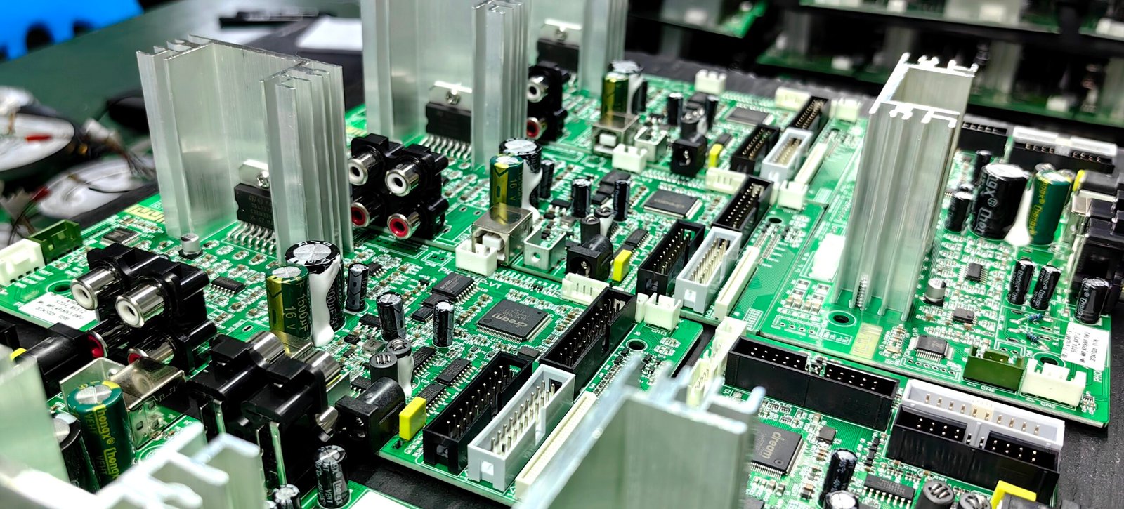
Keyboard/controller boards often mix:
SMT components (MCU, ESD devices, LEDs, connectors)
Through-hole components or socket modules
Optional programming and functional testing
HCJMPCBA describes capabilities such as multi-layer PCB manufacturing and assembly services with AOI/ICT quality controls and turnkey processes. HCJM PCBA
For socket-heavy builds, process control is everything: consistent soldering profile, controlled insertion, and inspection gates.
To lower procurement anxiety, many buyers write requirements like:
“Inspection per IPC-A-610 (Class 2 or Class 3 as agreed)”
“Soldering process aligned to J-STD-001 requirements”
“Provide traceability by lot/date code for critical parts where available”
“Provide AOI records and final functional test summary”
This turns “quality” from a promise into a measurable deliverable.
A procurement-friendly delivery package often includes:
Build traveler / process record (IQC → IPQC → FQC checkpoints)
AOI photos or pass/fail summaries
ICT/functional test report (as applicable)
Packaging controls (ESD-safe packing)
Traceability documentation for critical parts (per agreement)
Not in the keyboard sense. The extra “pins” are usually plastic support legs, so the benefit is stability, not extra electrical features.
Usually yes, because the 5-pin footprint contains the holes needed for the 3-pin geometry.
Often only after clipping the two extra plastic support legs (mechanical).
It means the PCB uses sockets so switches can be replaced without soldering; production must control insertion angle and socket solder integrity to prevent intermittent contact.
At minimum: acceptance criteria aligned with IPC-A-610, solder process discipline aligned with J-STD-001, and traceable reporting for critical parts and test results.
A 3 pin vs 5 pin switches decision is rarely about “which switch is more advanced.” For keyboard products, pin count mostly describes mounting stability and footprint compatibility. The real engineering work is choosing a footprint strategy (universal vs optimized), controlling installation on PCB and sheet materials (plate), and building a manufacturing process that protects sockets, pins, and pads.
For OEM programs, HCJMPCBA can support that process with DFM reviews, controlled assembly, inspection gates, and procurement-friendly documentation—so your keyboard/controller project scales with fewer surprises and less rework.
To learn more PCBA services, please contact Guangzhou Huachuang Precision Technology.
Discover what a gerber file is, why it is the universal “language” for PCB manufacturing, how to
This article provides a comprehensive overview of PCB and PCBA, their significance, manufacturing pr
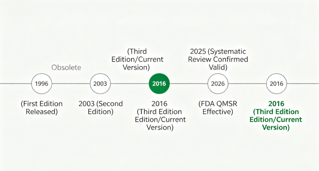
ISO 13485:2016 remains the current medical device quality standard, reaffirmed in 2025. But February