7 Professional Strategies for PCB Functional Testing: The Ultimate Engineering Guide to Zero-Defect Manufacturing
Master pcb functional testing and learn how to test a pcb board for high-reliability electronics. Th
A Yagi antenna is an “old-looking” structure—metal rods on a boom—yet it remains one of the most practical ways to improve reception or link reliability when signals are weak, noisy, or coming from a known direction. The reason is straightforward: a directional antenna concentrates energy. Instead of listening (or transmitting) equally in all directions, it focuses sensitivity in one direction and reduces interference from others. That’s why yagis are still common for an old television antenna setup, rural TV reception, point-to-point wireless links, and tracking systems.
People search this topic using many names—what is yagi, what is a yagi, yagi meaning, yagi aerial, yagi antena, or antena yagi uda—but they all point to the same core idea: a simple directional array made from one fed element and several passive elements.
A Yagi–Uda antenna (often shortened to yagi antenna) is a directional antenna made of two or more parallel resonant elements arranged in an end-fire array: one driven element connected to the feedline, plus parasitic elements (usually one reflector and one or more directors) that are not electrically connected but re-radiate energy to shape the pattern.
Directionality: a strong forward main lobe, weaker response behind and to the sides.
Practical gain: adding parasitic elements generally increases gain (with trade-offs).
Narrower bandwidth compared with some alternatives: the basic form is typically narrowband (good when the channel/frequency is known).
The driven element (the only fed radiating element)
The driven element is the part connected to the transmission line (feedline). In many designs it is a half-wave dipole or folded dipole. It sets the reference resonance and is the “engine” that creates the field that the other elements interact with.
The reflector (behind the driven element)
A reflector is typically slightly longer than the driven element and placed behind it (opposite the direction of intended radiation). Its job is to reduce radiation to the rear and reinforce forward radiation.
The directors (in front of the driven element)
Directors are typically slightly shorter and placed in front of the driven element in the intended direction. Adding directors usually increases forward gain and narrows the beam, which can be valuable for long links but increases aiming sensitivity.
A yagi-uda array works because the passive elements re-radiate energy they receive from the driven element, and their lengths/spacings cause the re-radiated fields to add more strongly in one direction and weaken in the opposite direction. The resulting yagi antenna radiation pattern is typically unidirectional with the main lobe off the end where the directors sit.
Even without deep antenna theory, a pattern plot tells engineers and buyers the information that matters:
Main lobe direction: where the antenna “looks” best (boresight).
Beamwidth: how precise aiming needs to be. Narrower beamwidth can mean better selectivity but more alignment sensitivity.
Front-to-back ratio: how much the antenna rejects signals from behind (useful for interference reduction).
Side lobes: unwanted sensitivity to off-axis directions; can matter in dense environments.
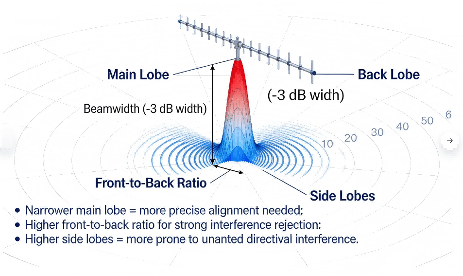
Yagi Radiation Pattern Interpretation Diagram
The most familiar form is the rooftop yagi tv antenna (sometimes called a yagi aerial), used to pull weak broadcast signals from a distant tower. The directional nature helps in rural areas or where buildings and terrain reduce signal strength.
Point-to-point links: when direction beats “coverage”
In wireless networking or industrial telemetry, a yagi antenna can create a stable point-to-point link by focusing the link budget in one direction and rejecting interference. It is often used when the far endpoint is fixed and known.
Tracking and measurement workflows
Researchers use yagis in wildlife tracking to direction-find a transmitter, because the pattern makes it easier to infer direction by rotating the antenna and observing signal strength changes.
VHF/UHF/FM variants: fm yagi antenna and yagi uhf antenna
Yagi–Uda designs are common across VHF and UHF. In practice, an fm yagi antenna targets a VHF band, while a yagi uhf antenna targets UHF reception or links. The structure stays similar; the physical sizes scale with wavelength.
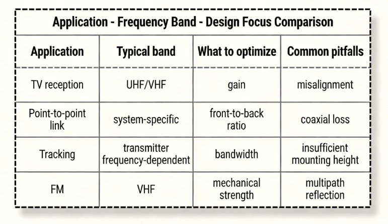
Yagi–uda Comparison Table Of Application Frequency Band Design Focus
Range depends on many factors: antenna gain, transmitter power, frequency, height, obstructions, and alignment. RayPCB notes that range is not one definitive number; real-world performance depends on environment and system parameters.
A more useful approach is to separate:
Line-of-sight geometry: height and curvature limits. RayPCB gives an example calculation that a 10 m height could yield roughly ~22 km line-of-sight under idealized assumptions.
Link budget: gains/losses across the chain (antenna gain, feedline loss, path loss, receiver sensitivity).
Alignment & multipath: directionality helps reject interference, but misalignment can erase gains quickly.
This is why two “identical” yagis can behave very differently after installation.
A Yagi is usually the better choice when:
The signal source (or destination) is in a known direction.
Interference rejection matters.
Range stability is more valuable than 360-degree coverage.
An omnidirectional antenna is usually the better choice when:
The source direction changes.
You need broad coverage without aiming.
Multiple devices connect from different directions.
One explains that yagis perform best with a clear line of sight, but can still function in non-line-of-sight situations with reduced range and potential multipath interference.
That matches real deployments: when buildings, trees, or terrain block the direct path, signals may arrive through reflections or diffraction. Results become more variable, and installation becomes more about finding the best practical placement.
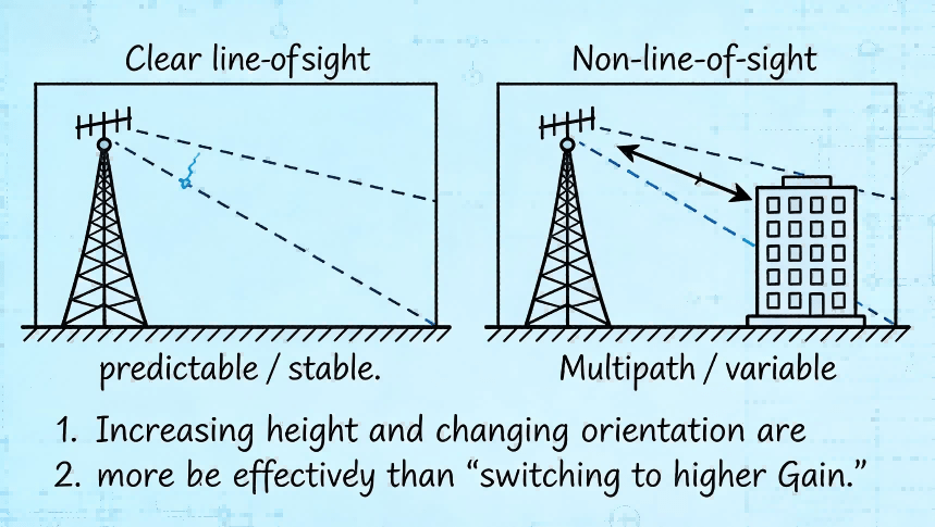
Yagi Antennas Comparison Chart Of Two Installation Environments
A yagi can work without grounding, but grounding is generally recommended in permanent outdoor installations for safety and (sometimes) noise reduction. RayPCB lists typical reasons: lightning protection, static electricity dissipation, noise reduction, and compliance with local requirements.
One describes common methods such as connecting the mast to an earth ground rod or bonding to the building’s grounding system, while emphasizing correct technique and low resistance paths.
Because codes vary by location and building type, installers should follow applicable electrical and building regulations.
This section is written to be usable for engineering planning and procurement discussions. It focuses on decisions and parameters rather than abstract theory.
Step 1 — Define the target frequency and bandwidth
Start with the frequency (or channel range) the antenna must cover. The Yagi–Uda is often narrowband: Wikipedia notes the basic form can be around 2–3% of the center frequency by one definition, and that there is a gain–bandwidth tradeoff as more elements are used.
If the application is a single channel or narrow band: a classic yagi is usually a good fit.
If the application spans a wide band: expect compromises, or a design that intentionally broadens bandwidth (for example, TV-oriented structures can differ).
Step 2 — Choose element count (performance vs size)
For many practical builds, a 3–6 element Yagi is a good balance of size and performance.
More elements can increase gain, but returns diminish and alignment becomes more critical.
A useful planning question is: Does the use case need more gain, or does it need less loss and cleaner installation? Often, improving feedline quality and mounting height beats adding two more directors.
Step 3 — Estimate wavelength and “first-cut” element lengths
Wavelength (λ) ≈ c / f, where c is the speed of light and f is frequency. That sets the physical scale.
Wikipedia notes Yagi elements are typically around half-wave in length, and that reflector(s) are slightly longer while directors are slightly shorter than the driven element.
RayPCB provides a more concrete rule-of-thumb: the reflector about 5% longer and directors progressively shorter.
This is enough to get a first-cut mechanical layout before simulation and tuning.
Step 4 — Set element spacing (first-cut values that usually work)
Spacing strongly affects gain, impedance, and pattern.
Wikipedia notes typical spacings vary from about 1/10 to 1/4 of a wavelength, depending on design.
One offers practical starting numbers: driven-to-reflector spacing around 0.2 to 0.25 λ, and director-to-director spacing around 0.3 to 0.4 λ.
These are “start here” values—not final answers. The right spacing is what meets the performance goals after tuning.
Step 5 — Decide on feed and impedance matching
Matching is where many “it looks right but performs badly” builds fail.
One notes a typical Yagi feedpoint impedance can be low (around 20–30 ohms) and that matching methods like gamma or hairpin matches are used to bring it closer to 50 ohms for standard coaxial cable.
In TV-style systems you may also encounter 75-ohm ecosystems; in either case, the principle is the same: reduce reflections so more power reaches the antenna and less comes back.
A simple way to explain this to non-RF stakeholders: matching is like making sure pipes are the right diameter so flow doesn’t “bounce back.”
Step 6 — Simulate, prototype, and tune
Simulation tools help explore element lengths/spacings quickly, but real-world tuning is still common because nearby structures, mounting, and material choices can shift resonance. RayPCB recommends using modeling software to fine-tune spacing and overall performance.
For practical tuning, teams often measure:
Return loss or voltage standing wave ratio (a reflection indicator),
Forward gain and front-to-back ratio (pattern behavior),
Stability after mounting and cabling.
Step 7 — Validate installation, not just the antenna
Many “design problems” are installation problems:
Coaxial cable loss at the target frequency,
Connector quality and strain relief,
Boom and bracket interaction,
Aiming repeatability and wind loading.
This template is intentionally “first-cut.” It creates a shared language between engineering, sourcing, and manufacturing before final tuning.
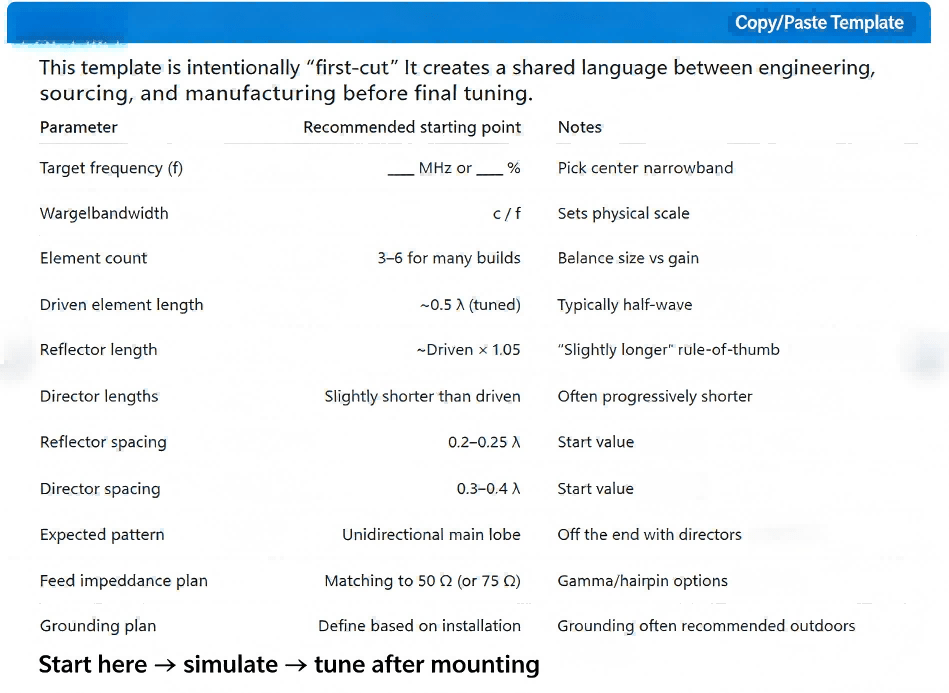
Yagi–uda Engineering Template Diagram
Mistake: assuming “more directors = always better”
More directors usually increase forward gain but also reduce beamwidth, tighten tolerances, and increase sensitivity to aiming and installation. Wikipedia notes gain tends to increase with more parasitic elements, but also discusses trade-offs (including bandwidth narrowing).
Fix: keep element count modest unless there is a measured reason to grow it.
Mistake: ignoring feedline and connector loss
A perfect antenna with a lossy cable behaves like a mediocre antenna.
Fix: choose appropriate coax and connectors for the frequency and outdoor conditions; keep runs short.
Mistake: tuning in free space but installing near metal structures
Nearby conductive structures can distort the yagi radiation pattern and shift resonance.
Fix: validate after mounting; adjust if needed.
Mistake: skipping grounding and surge protection in permanent outdoor installs
One explains grounding is generally recommended for safety (lightning/static) and can help with noise.
Fix: include grounding and protective practices aligned with local requirements.
Yagi–Uda / yagi-uda / uda yagi / uda antenna: the same antenna family, named after the original inventors.
Yagi aerial / old television antenna / yagi tv antenna: common consumer descriptions of a rooftop Yagi used for TV.
Yagi antena / antena yagi uda: common non-English query forms that refer to the same design.
“Jungle antenna”: sometimes used colloquially online to mean “an outdoor directional TV antenna,” but not a formal engineering term.
If someone arrived here from a pop-culture query like “rod of cancellation 2e wiki,” that phrase is unrelated to RF engineering; the Yagi here is strictly an antenna design.
A Yagi antenna is often a mechanical structure, but many real products around it still require electronics: matching networks, RF filtering, power conditioning, connectors, and enclosure integration. Those electronics are where procurement risk often shows up—counterfeit parts, uncontrolled impedance, inconsistent solder quality, or missing test documentation.
HCJMPCBA positions its capabilities as “one-stop” printed circuit board manufacturing and printed circuit board assembly services, including surface-mount technology assembly, through-hole assembly, testing, and box-build integration.
Controlled geometry and build parameters: HCJMPCBA publishes quantified manufacturing capability ranges (for example, multi-layer capability and line width/spacing specifications across board types).
Placement and soldering precision for RF support electronics: their capability page lists quantified placement accuracy and assembly metrics for surface-mount technology and ball grid array packages.
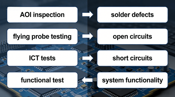
Testing and reporting: their assembly services page describes testing steps such as automated optical inspection, in-circuit testing, and functional validation as part of turnkey workflow.
If a buyer’s goal is to reduce risk, the most practical trust signals are not slogans—they are certifications, measurable process capability, and documentation.
HCJMPCBA’s published compliance section includes ISO 9001 and ISO 13485, and also lists additional compliance items (such as RoHS and others) on its capabilities page.
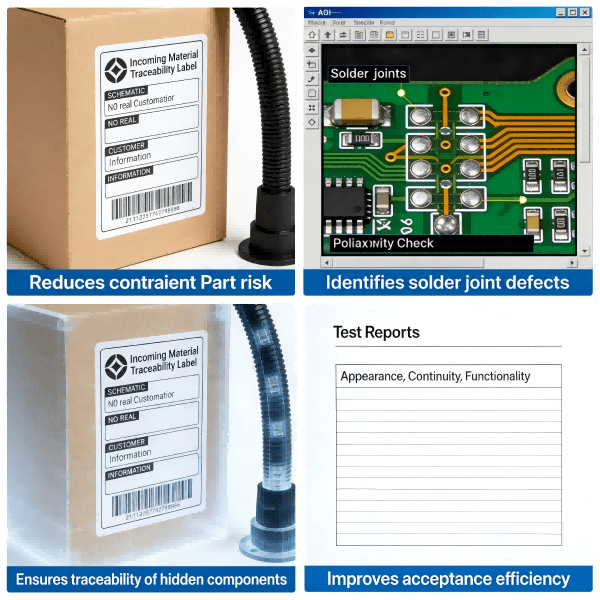
Rf Product Delivery Evidence Package
Q1) What is yagi antenna and why is it directional?
A yagi antenna is a Yagi–Uda array: one driven element plus parasitic elements that reradiate and shape a unidirectional pattern, with strongest radiation off the end where the directors are placed.
Q2) Are yagi antennas only for TV?
No. TV reception is a classic use, but yagis are also used for point-to-point links, signal boosting, and tracking applications.
Q3) What does a yagi antenna radiation pattern tell you?
It shows where the antenna is most sensitive (main lobe), how narrow the beam is (beamwidth), and how well it rejects signals from behind (front-to-back ratio).
Q4) Does a yagi need line of sight?
It performs best with line of sight, but can still function without it—usually with reduced range and more variable behavior due to obstacles and multipath.
Q5) Do I need grounding for a yagi tv antenna?
Grounding is generally recommended for permanent outdoor installs due to lightning/static safety and potential noise benefits; follow local requirements and correct techniques.
A Yagi–Uda (yagi-uda / uda yagi) remains one of the most practical directional antenna designs because it delivers useful forward gain with a relatively simple structure: one driven radiating element plus parasitic elements that shape the yagi radiation pattern. Wikipedia summarizes the essentials—directors slightly shorter, reflector slightly longer, typical spacings on the order of a fraction of a wavelength—and also highlights the real trade-off engineers manage: as gain increases with more parasitic elements, bandwidth typically narrows.
Design success comes from disciplined steps—define frequency and bandwidth, choose element count, set first-cut lengths and spacing, match impedance, then validate after installation and grounding practices.
Master pcb functional testing and learn how to test a pcb board for high-reliability electronics. Th
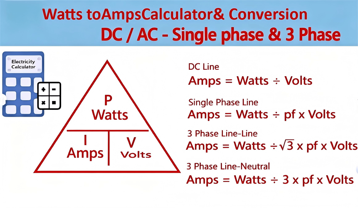
Learn exactly how to convert watts to amps in DC, single-phase AC, and three-phase systems with clea
This article analyzes the future trends of the electronic manufacturing industry, including technolo