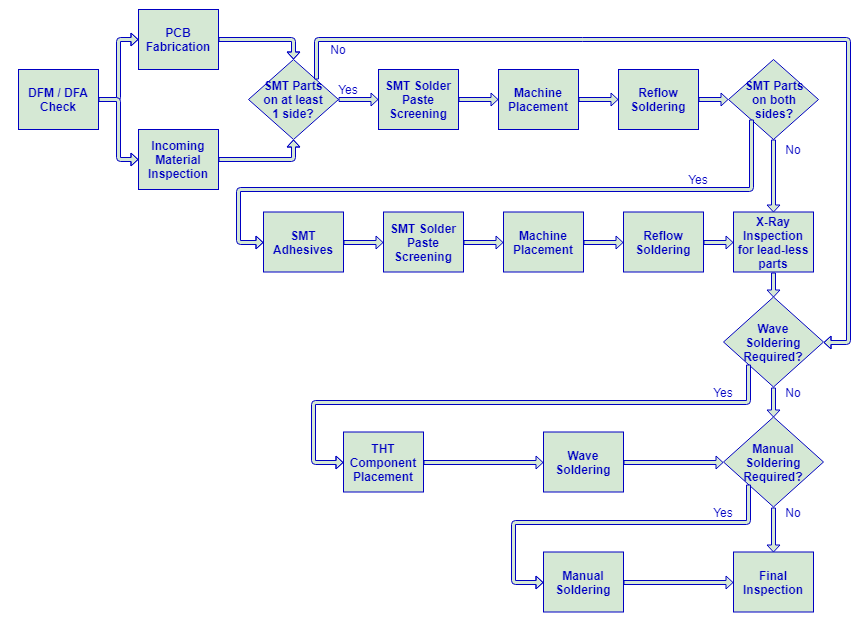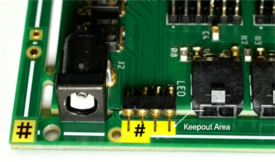
Why Is a Keepout on the PCB? 7 Key Reasons & Best Practices
A keepout on a PCB is a software-enforced exclusion zone that prevents copper, vias, or components i
Bismaleimide-Triazine (BT) resin is a high-performance thermoset material widely used in the PCB industry, particularly for IC packaging and high-frequency applications. Developed primarily from a combination of bismaleimide and cyanate ester (Triazine), BT resin offers a unique balance of thermal, mechanical, and electrical properties that far exceed standard FR-4 materials.
At HCJMPCBA, we specialize in processing BT-based laminates (such as the Mitsubishi Gas Chemical HL832 series) to support next-generation semiconductor packaging.
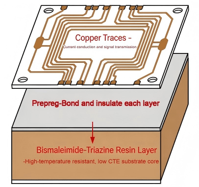
Simple Bismaleimide Triazine Bt Pcb Structure Diagram
Why is Bismaleimide-Triazine the preferred choice for hardware engineers?
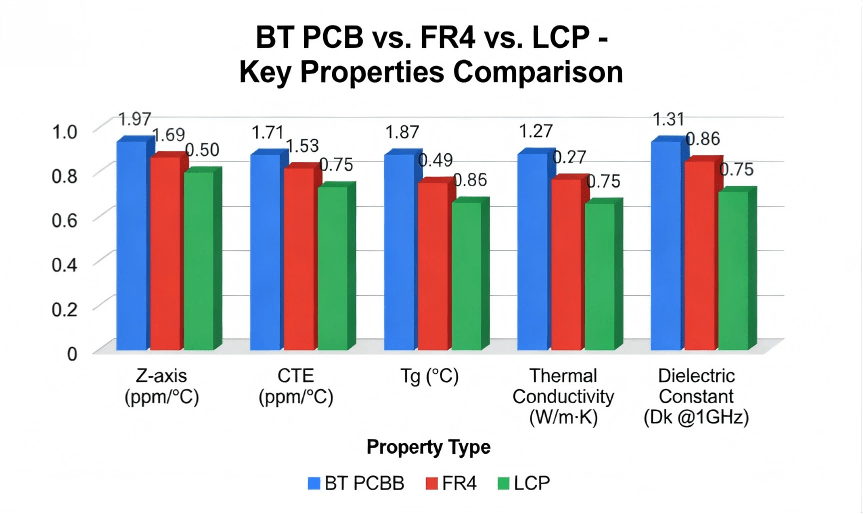
Exceptional Thermal Stability: BT resins feature a high Glass Transition Temperature (Tg) ranging from 180°C to 240°C, ensuring structural integrity during high-temperature lead-free soldering processes.
Low Dielectric Constant (Dk) & Dissipation Factor (Df): With a Dk around 3.3–3.8 and Df near 0.003, BT PCBs are ideal for high-speed signal transmission and mmWave applications.
Superior Moisture Resistance: Unlike Polyimide, BT resin has extremely low water absorption, preventing “popcorn” effects during SMT reflow.
Anti-CAF (Conductive Anodic Filament) Resistance: The chemical structure provides excellent insulation reliability, crucial for fine-pitch IC substrates.
Low CTE (55 ppm/°C below Tg): When PCBA undergoes thermal cycling (e.g., an automotive component heating up when the engine runs, then cooling down when turned off), the substrate and copper traces expand/contract at different rates. A low CTE means less stress on copper vias and solder joints—reducing the risk of cracks or open circuits.
High Tg (180°C): In high-temperature environments (e.g., industrial ovens, engine compartments), BT PCB stays rigid and stable. Standard FR4 would soften above 130°C, leading to warping or short circuits.
Thermal Conductivity (0.35 W/m·K): For power-hungry components (e.g., microprocessors in industrial PLCs), BT PCB dissipates heat faster than FR4. This keeps components cool and extends their lifespan.
Bt Pcb Vs. Other Substrates
| Feature | BT (Bismaleimide-Triazine) | Standard FR-4 |
| Glass Transition (Tg) | 180°C – 240°C | 130°C – 170°C |
| Dielectric Constant (Dk) | 3.3 – 3.8 (@1GHz) | 4.2 – 4.8 (@1GHz) |
| Dissipation Factor (Df) | 0.003 – 0.006 | 0.015 – 0.020 |
| Moisture Absorption | < 0.1% | 0.2% – 0.5% |
| Main Application | IC Substrates, BGA, CSP | Motherboards, Consumer Electronics |
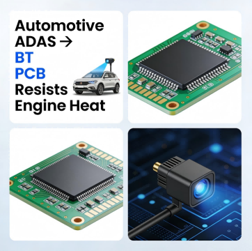
Automotive Electronics: Engine control units (ECUs), ADAS sensors, and electric vehicle (EV) battery management systems (BMS) operate in high-heat, high-vibration environments. BT PCB’s low CTE and high Tg prevent solder joint failure.
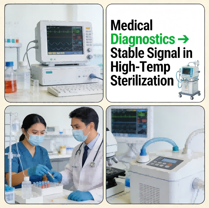
Medical Devices: Diagnostic equipment (e.g., ultrasound machines) and implantable devices (e.g., pacemakers) need biocompatible, stable substrates. BT PCB meets medical-grade standards (ISO 13485) and resists body fluids/chemicals.
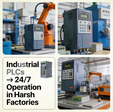
Industrial Control: PLCs (Programmable Logic Controllers), sensors for manufacturing lines, and power inverters run 24/7 in dusty, high-temperature factories. BT PCB’s durability reduces unplanned downtime.
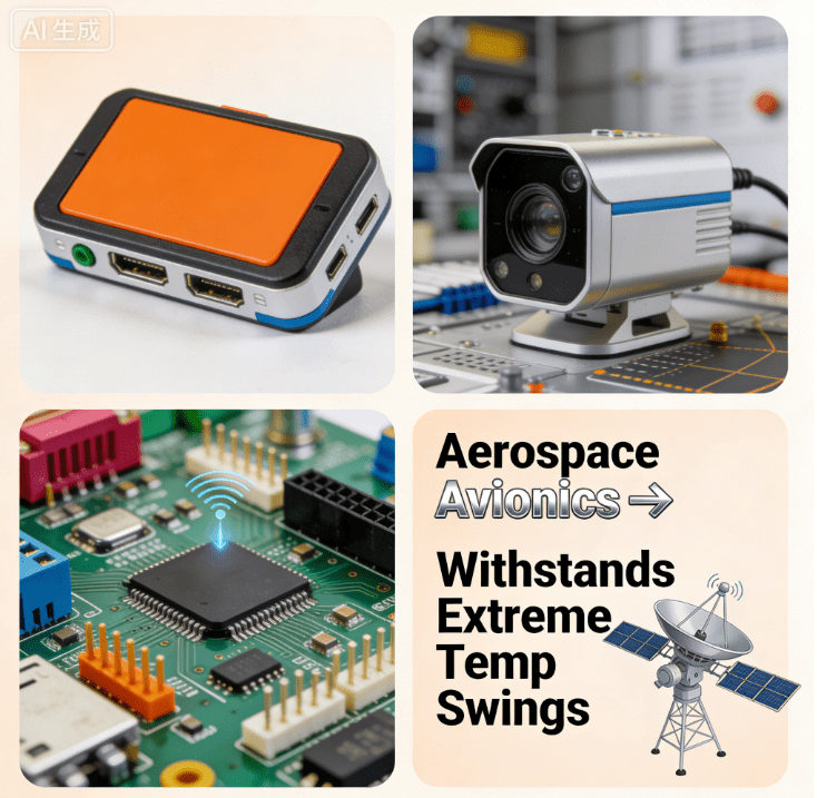
Aerospace & Defense: Avionics systems (e.g., navigation controls) need substrates that withstand extreme temperature swings (-55°C to 150°C) and radiation. BT PCB’s decomposition temperature (325°C) and mechanical strength make it a fit.
Consumer electronics (e.g., smart home devices, tablets) where operating temps are mild (-10°C to 60°C).
Low-volume, cost-sensitive prototypes (BT PCB’s higher cost would eat into budget).
Simple circuits with no high-power or high-frequency components (e.g., basic LED controllers).
Resin Mixing: Bismaleimide and triazine monomers are mixed with a catalyst to form a viscous resin. We use high-purity monomers (99.9% purity) to avoid impurities that cause defects.
Impregnation: Glass cloth (typically E-glass for mechanical strength) is dipped into the BT resin. The cloth absorbs the resin evenly—critical for consistent dielectric properties across the substrate.
Lamination: The resin-impregnated cloth (called “prepreg”) is stacked with copper foils (1oz–4oz thickness) and pressed at high temperature (200–220°C) and pressure (30–50 kg/cm²) for 60–90 minutes. This cures the resin into a rigid, heat-resistant substrate.
Trimming & Inspection: The laminated BT PCB is trimmed to size, and we use X-Ray inspection to check for internal voids (a common issue with high-Tg resins). Any substrates with voids >0.1mm are rejected.
SMT Pick-and-Place: Our high-speed SMT machines (Yamaha YSM40R) use precision nozzles (0.3mm diameter) to place components on BT PCB. The substrate’s flatness (tolerance ±0.1mm) ensures accurate component alignment.
Reflow Soldering: We use 13-zone reflow ovens with a customized temperature profile for BT PCB: preheat (150–180°C for 60s), soak (180–200°C for 40s), peak (240–250°C for 10s). This avoids overheating the BT resin while ensuring solder joints fully form.
DIP Wave Soldering: For through-hole components, our wave soldering machines run at 250–260°C (5–10°C higher than FR4) to account for BT PCB’s higher thermal conductivity. We also use a nitrogen atmosphere to prevent solder oxidation.
SPI (Solder Paste Inspection): Before reflow, we use 3D SPI machines to check solder paste volume and alignment (tolerance ±10μm). This prevents cold solder joints on BT PCB.
AOI (Automated Optical Inspection): After SMT, AOI machines scan for component misalignment, missing parts, or solder defects (e.g., bridging). BT PCB’s light color (off-white) makes defects easier to detect.
X-Ray Inspection: For BGA (Ball Grid Array) components, X-Ray checks for hidden solder voids (max 15% void area per joint—stricter than the industry standard of 25%).
Thermal Cycling Test: We subject 5% of BT PCB-based PCBA to 1,000 thermal cycles (-40°C to 125°C, 30min/cycle) to simulate real-world use. Only PCBA with 0 failures pass.
Electrical Testing: Each PCBA undergoes ICT (In-Circuit Testing) to check for short circuits, open circuits, and component functionality. For high-frequency PCBA, we also perform RF testing (up to 6 GHz) to verify signal integrity.
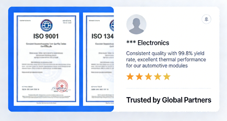
Client Example: A global EV manufacturer needed a BMS (Battery Management System) PCB that could withstand the heat of lithium-ion batteries (up to 120°C) and resist vibration. We used BT PCB with 2oz copper traces (for high current) and added a conformal coating (to protect against moisture). The result: 99.9% yield and zero field failures over 2 years.
Key BT PCB Benefits: High Tg (180°C) resists battery heat; low CTE (55 ppm/°C) prevents solder joint cracks from vibration; flame retardancy (UL 94 V0) meets automotive safety standards.
Applications And Advantages Of Bt Pcb In Different Industries1
Client Example: A medical equipment maker needed a PCB for a portable ultrasound machine. The PCB had to be small (100x80mm), lightweight, and operate in hospitals (temp 18–25°C, but sterilization cycles up to 134°C). We used thin BT PCB (0.8mm thickness) with HDI (High-Density Interconnect) technology to fit more components. The PCB passed ISO 13485 audits and FDA certification.
Key BT PCB Benefits: Biocompatible resin (no toxic additives); stable dielectric properties (no signal interference for ultrasound); ability to integrate HDI (for miniaturization).
Applications And Advantages Of Bt Pcb In Different Industries2
Client Example: A factory automation company needed a PLC PCB for a metal stamping line. The PLC operates in a 40–60°C environment with high vibration. We used BT PCB with a metal core (for extra heat dissipation) and reinforced solder joints. The PLC has run continuously for 3 years with no downtime.
Key BT PCB Benefits: Thermal conductivity (0.35 W/m·K) dissipates heat from the processor; mechanical strength resists vibration; chemical resistance (to oil and dust).
Applications And Advantages Of Bt Pcb In Different Industries3
Client Example: A defense contractor needed a PCB for a satellite navigation system. The PCB had to withstand -55°C (in space) to 125°C (during launch) and resist radiation. We used radiation-hardened BT PCB with gold-plated copper traces (for corrosion resistance). The PCB passed MIL-STD-883H testing (aerospace standard).
Key BT PCB Benefits: High decomposition temperature (325°C) resists launch heat; low outgassing (no volatile compounds in space); radiation resistance (protects against cosmic rays).
Applications And Advantages Of Bt Pcb In Different Industries4
Design Support (DFM): Our engineers review your PCB design for BT compatibility (e.g., trace width, via size) and provide feedback within 24 hours. For example, we’ll suggest increasing via diameter from 0.2mm to 0.3mm for BT PCB (to avoid drilling cracks).
Substrate Sourcing: We work with 3 trusted BT resin suppliers (including Ajinomoto) to ensure consistent quality. We also stock standard BT PCB sizes (100x150mm, 150x200mm) to reduce lead times.
Assembly & Testing: As a one-stop shop, we handle SMT, DIP, assembly, and testing—no need to work with multiple vendors. This reduces communication gaps and improves quality control.
Packaging & Shipping: We use anti-static packaging and temperature-controlled shipping for BT PCB-based PCBA (critical for long-distance deliveries).
SMT Lines: 4 high-speed SMT lines (Yamaha YSM40R, JUKI RS-1R) with a daily capacity of 800,000 solder points. These machines can place components as small as 01005 (0.4×0.2mm) on BT PCB.
Lamination Equipment: 2 high-temperature lamination presses (220°C max) for custom BT PCB substrates. We can produce BT PCB thicknesses from 0.4mm to 6.5mm.
Testing Labs: In-house labs with SPI, AOI, X-Ray, and thermal cycling equipment. We also partner with third-party labs (e.g., TUV Rheinland) for certification testing (e.g., MIL-STD, ISO 13485).
Prototypes: 3–5 days (from design approval to PCBA delivery).
Small Batches (10–100 units): 7–10 days.
Large Batches (1,000+ units): 15–20 days.
For emergency projects (e.g., medical device repairs), we offer a 24-hour 加急 service (with priority production).
Custom Substrates: We can produce BT PCB with special features (e.g., metal cores, HDI, conformal coatings) to meet your application’s needs.
Low-Volume Orders: Unlike many manufacturers that require minimum orders of 100+ units, we accept BT PCB prototypes starting at 1 unit. This is ideal for R&D teams testing new designs.
Global Compliance: We ensure BT PCB-based PCBA meets regional regulations (e.g., RoHS for Europe, FDA for the US, CCC for China). Our team stays updated on new standards (e.g., IATF 16949 for automotive) to keep your products compliant.
ISO 9001: Quality management system (ensures consistent production).
ISO 13485: Medical device quality management (for BT PCB used in healthcare products).
IATF 16949: Automotive quality management (for automotive BT PCB applications).
RoHS & REACH: Compliance with European chemical regulations (no lead, mercury, or other toxic substances).
UL 94 V0: Flame retardancy certification for BT PCB (critical for safety-critical applications).
Patent #CN202310542178.9: “A BT PCB Substrate with Enhanced Thermal Conductivity” (uses a ceramic filler to boost heat dissipation).
Patent #CN202221876543.2: “HDI BT PCB for Miniaturized Medical Devices” (integrates microvias for smaller, more dense PCBA).
Patent #CN202110987654.1: “Thermal Cycling Resistant BT PCB Solder Joints” (improves solder joint durability in high-heat applications).
Client Satisfaction: 98% of our BT PCB clients return for repeat projects. We regularly survey customers and use feedback to improve our processes.
Case Studies: We’ve published 15+ case studies on BT PCB projects (e.g., “How We Reduced a Medical Client’s BT PCB Failure Rate to 0.1%”). You can read these on our website or request a custom case study relevant to your industry.
Referenceable Clients: We’re proud to work with leading companies in automotive (e.g., a top 5 global EV maker), medical (e.g., a Fortune 500 healthcare firm), and industrial (e.g., a major factory automation provider). We can connect you with references upon request.
Warranty: We offer a 2-year warranty on all BT PCB-based PCBA (double the industry average of 1 year). If a PCBA fails due to manufacturing defects, we’ll repair or replace it for free.
Lifetime Technical Support: Even after the warranty expires, our engineers are available to answer your BT PCB questions (e.g., “How do I maintain this PCBA in a high-heat environment?”). We also provide maintenance guides and troubleshooting tips for your team.
Root Cause Analysis: If a failure occurs, we conduct a full root cause analysis (using X-Ray, AOI, and thermal testing) to identify the issue and prevent it from happening again. We share the analysis report with you and adjust our processes if needed.
Product Quality And Market Feedback
A 100x150mm, 1.6mm thick, 2-layer FR4 PCB costs ~$2–$3.
The same size and specs for BT PCB cost ~$5–$9.
The higher cost comes from the premium resin (bismaleimide-triazine) and more complex lamination process. However, the cost is often justified by reduced field failures and longer product lifespan.
Prototypes (1–10 units): 3–5 days.
Small batches (10–100 units): 7–10 days.
Large batches (100+ units): 15–20 days.
For emergency orders (e.g., critical medical device repairs), we offer a 24-hour urgent service (additional fee applies).
Storage: BT PCB should be stored in a dry environment (humidity <50%) at room temperature (20–25°C). Exposure to moisture can cause delamination during reflow.
Drilling: Use carbide drills with a 130–140° point angle (sharper than FR4 drills) to avoid resin chipping. We also recommend using a cooling spray during drilling to prevent heat buildup.
Soldering: Use a higher reflow peak temperature (240–250°C) than FR4 (220–230°C) to ensure proper solder wetting. Avoid prolonged exposure to high temperatures (keep peak time <15s) to prevent resin degradation.
Operates in high temperatures (>120°C) or extreme thermal cycles (-40°C to 125°C).
Requires low signal loss (high-frequency applications like ADAS or medical imaging).
Needs to resist vibration, chemicals, or radiation (industrial, aerospace, or medical use).
Has a long lifespan (5+ years) with minimal maintenance (e.g., automotive ECUs, industrial PLCs).
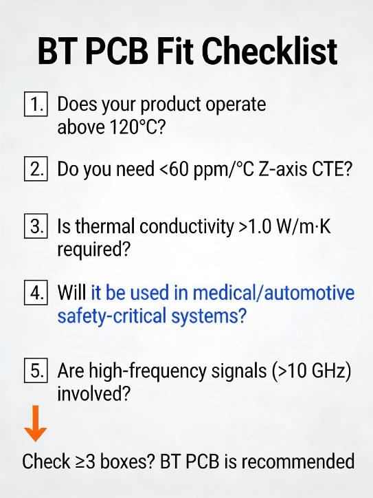
Bt Pcb Applicability Checklist
A keepout on a PCB is a software-enforced exclusion zone that prevents copper, vias, or components i

Discover HCJMPCBA’s 13485 medical manufacturing excellence in medical PCB assembly. Learn about me
Learn exactly how to convert watts to amps in DC, single-phase AC, and three-phase systems with clea