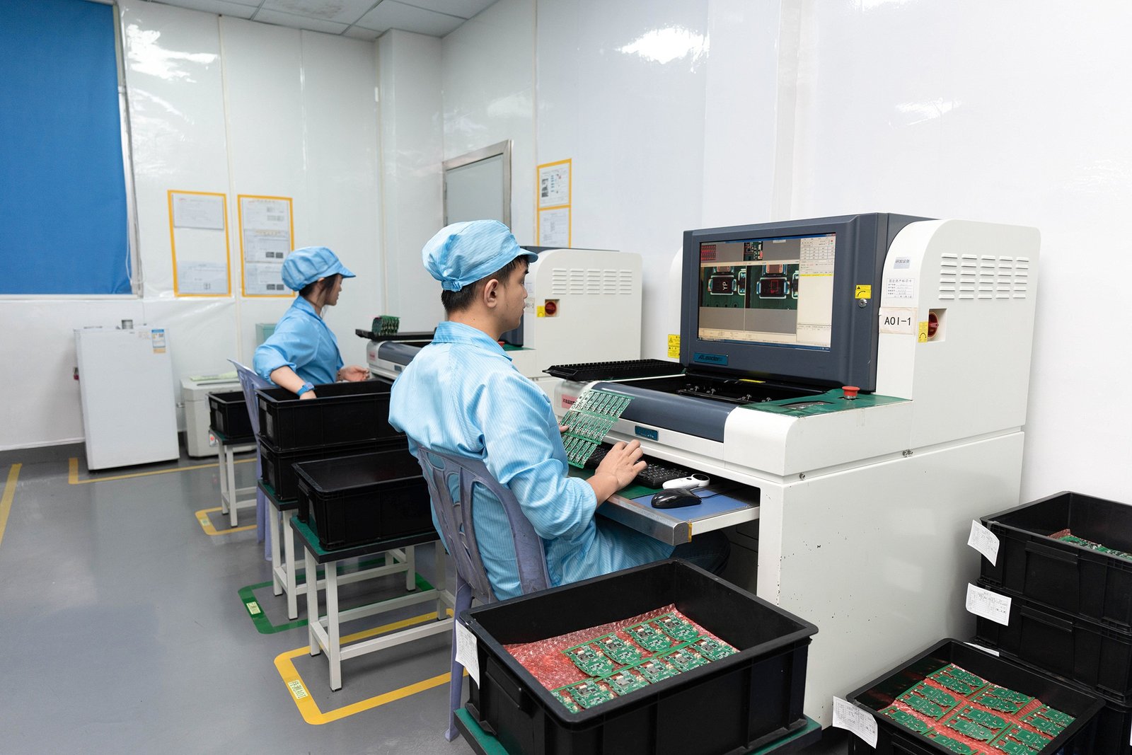
AOI Inspection PCB: 7 Powerful Insights into Automated Optical Inspection in PCB Manufacturing
Automated Optical Inspection (aoi inspection pcb) is a non-contact, high-speed quality control metho
A digital thermometer circuit diagram is a technical blueprint that defines the electrical connections between a temperature sensor (like an LM35 or thermistor), a microcontroller (often an arduino thermometer sensor), and a display unit. At HCJMPCBA, we treat every thermometer drawing as a production-ready document, ensuring it meets IPC-6012 standards and includes a specific method number + revision for lifecycle management. This guide is maintained by the HCJMPCBA engineering team and updated with production checklists.
1.Precision Starts at the Schematic: A thermometer drawing is more than just lines; it is the foundation for signal integrity and thermal management in PCBA.
2.Traceability is Non-Negotiable: For industrial and medical applications of digital thermometer, knowing the lot/batch/serial of every component is the only way to ensure long-term reliability.
3.DFM (Design for Manufacturing) Integration: Converting an easy thermometer drawing into a scalable product requires strict adherence to method number revisions and verified raw data.
To understand what is digital thermometer technology, one must look at the conversion of physical energy into digital data. Unlike analog thermometers that rely on the expansion of mercury, a digital version utilizes a circuit temperature sensor to detect changes in electrical properties.
Most digital thermometer how does it work explanations center on the relationship between temperature and resistance (in thermistors) or voltage (in IC sensors). For example, a Negative Temperature Coefficient (NTC) thermistor’s resistance decreases as temperature increases. The mathematical relationship is often defined by the Steinhart-Hart equation:
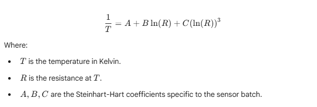
Digital Thermometer How Does It Work
At HCJMPCBA, when we receive a thermometer diagram, our engineers verify these coefficients against the sensor’s raw data to ensure the arduino temperature sensor code used in the firmware matches the physical board characteristics.
Choosing the right components during the drawing thermometer phase determines the end-product’s accuracy and cost-efficiency.
| Feature | Thermistor (NTC/PTC) | IC Sensor (LM35/TMP36) | RTD (PT100/PT1000) | Thermocouple |
| Accuracy | Medium | High | Very High | Medium |
| Temp Range | -55 to +150°C | -40 to +150°C | -200 to +600°C | -200 to +1800°C |
| Drawing Complexity | Easy thermometer drawing | Simple 3-pin setup | Complex (4-wire bridge) | High (Cold Junction) |
| Best Application | Food thermometer drawing | Temperature detector arduino | Industrial Labs | High-heat Furnaces |
When you decide to draw a thermometer for an OEM project, you must transition from a conceptual drawing of a thermometer to a technical thermometer drawing that a factory can actually build.
1.Define the Power Rail: Digital sensors are sensitive to noise. Your thermometer diagram must include decoupling capacitors (usually $0.1\mu F$ and $10\mu F$) placed as close to the MCU/Sensor as possible.
2.Signal Conditioning: If you are using an arduino thermometer sensor, the analog signal may need an Operational Amplifier (Op-Amp) to scale the voltage range for maximum resolution of the ADC (Analog-to-Digital Converter).
3.Reference Voltage (Vref): A stable digital thermometer using [Arduino] logic requires a precise reference voltage. Avoid using the default VCC if it is shared with noisy components like motors or backlights.
4.The Display Interface: Whether you choose an I2C OLED or a 16×2 LCD, ensure the drawing of thermometer includes the correct pull-up resistors (typically $4.7k\Omega$) for communication lines.
5.Protection Circuitry: For a food thermometer drawing, include ESD protection diodes on any probes that are external to the main housing.
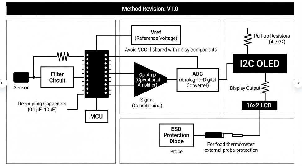
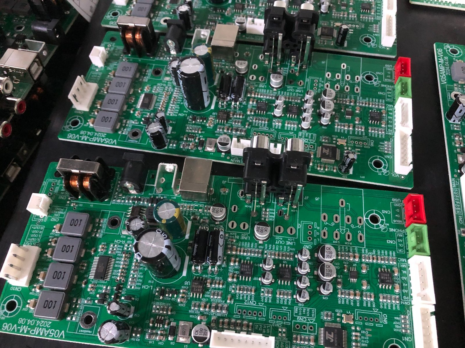
Thermometer Drawing Industrial Grade Schematic Layer Diagram
For a global procurement manager, the biggest risk is not knowing what happened during the assembly of their circuit temperature sensor. At HCJMPCBA, we eliminate this “black box” through a rigorous documentation framework.
Every thermometer easy drawing submitted to us is assigned a unique method number. This internal ID tracks the specific tooling, soldering temperatures, and assembly sequences used for your project. If you update your arduino temperature sensor code or change a resistor value, the revision history ensures that the factory floor never uses an outdated blueprint.
We don’t just “hope” it works. Our sample plan follows ISO 2859-1 (AQL) standards.
Visual Inspection: IPC-A-610 Class 2 or 3.
Functional Testing: Every digital thermometer how does it work verification includes testing at three temperature points: $0$°C (Ice Point), $37$°C (Body Temp), and $100$°C (Boiling Point).
Test Conditions: We document humidity, ambient temperature, and voltage stability during the test.
In 2026, traceability (lot/batch/serial) is the gold standard. If a sensor fails in the field, HCJMPCBA can trace that specific serial number back to its original batch from the component manufacturer. This allows for targeted recalls rather than catastrophic losses.
| Test Phase | Verification Method | HCJMPCBA Evidence Provided |
| PCB Fabrication | Flying Probe / AOI | E-Test Report & Microsection Data |
| Component Sourcing | Counterfeit Detection | Lot/Batch Certificate of Conformance |
| PCBA Assembly | 3D Solder Paste Inspection | SPI Raw Data |
| Final Calibration | Thermal Chamber Testing | Calibration Curve (V vs T) |
“The PCBA provider must provide full traceability (lot/batch/serial) for all active components and precision resistors. Manufacturing must follow Method Number [Insert ID] Revision [Insert Rev] with a documented sample plan. All functional test raw data must be archived and available for audit for 5 years.”
Even a professional thermometer drawing can fail if these nuances are ignored:
1.Thermal Parasitics: Placing the thermometer sensor arduino too close to the power regulator. This causes “self-heating,” leading to inaccurate readings.
2.Poor Trace Shielding: Running analog signal traces from the circuit temperature sensor parallel to high-speed digital lines without a ground plane.
3.Ignoring Voltage Drop: Using thin traces for the power supply, which can shift the reference voltage and ruin the ADC accuracy.
4.Inadequate Calibration: Relying on the theoretical datasheet values instead of performing a 2-point calibration in the software.
5.Neglecting Moisture: For food thermometer drawing applications, failing to specify conformal coating leads to short circuits in high-humidity environments.
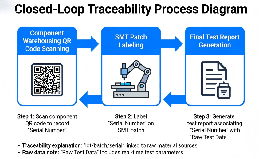
Thermometer Drawing Traceability Process Demonstration
Consider a medical-grade digital thermometer. The application of digital thermometer in a clinical setting requires accuracy within pm 0.1°C. An easy thermometer drawing used for a hobbyist project might fluctuate by \pm 2.0°C due to noise. When a client approached HCJMPCBA for a wearable fever tracker, we implemented a custom sample plan that tested 100% of the initial 500 units to establish a baseline of raw data before moving to a standard AQL.
Q1: What are digital thermometers made of?
A: They consist of a sensor (thermistor/RTD), a microcontroller (MCU), a power management circuit, and a display. The thermometer diagram links these via a PCB.
Q2: Can I use an arduino thermometer sensor for commercial products?
A: Yes, many commercial products use the ATmega or ARM chips found in Arduino. However, the thermometer drawing must be upgraded from a breadboard style to a professional PCB layout with proper EMI shielding.
Q3: How does a digital thermometer work in cold environments?
A: Components must be rated for the correct temperature range. We check the lot/batch data to ensure all capacitors and resistors are rated for “Industrial Grade” ($-40$ to $+85$°C).
Q4: Is it hard to draw a thermometer circuit?
A: An easy thermometer drawing is simple, but an industrial drawing of thermometer requires knowledge of signal integrity and PCB stack-up.
Q5: Why does HCJMPCBA require a method number?
A: The method number ensures consistency. It acts as a recipe for our machines, so the 1st board and the 10,000th board are identical.
Q6: What is the most accurate digital thermometer circuit?
A: Circuits using a 4-wire RTD (Resistance Temperature Detector) and a 24-bit ADC offer the highest precision.
Q7: How do I get the raw data from my PCBA production?
A: At HCJMPCBA, we provide digital logs of our automated test equipment (ATE) results for every batch.
When partnering with us for your digital thermometer circuit diagram implementation, you are entitled to:
DFM Feedback Report: Detailed analysis of your thermometer drawing.
Component Authenticity Reports: Traceability back to the original manufacturer.
AOI & X-Ray Images: Visual proof of soldering quality.
Calibration Raw Data: The actual voltage readings recorded during final QC.
Update triggers: standard revision changes / recurring questions / production checklist updates.
Automated Optical Inspection (aoi inspection pcb) is a non-contact, high-speed quality control metho
Guangzhou Huachuang Precision Technology Co.,Ltd.employs advanced X-RAY detection to provide non-des
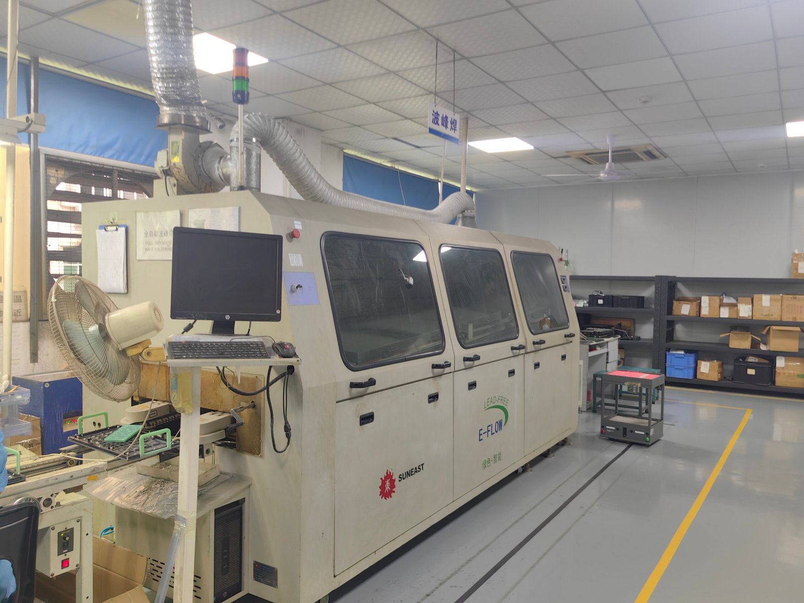
Guangzhou Huachuang Precision Technology Co., Ltd. utilizes advanced reflow soldering technology to


