For DC PCBA (the majority of consumer, IoT, and medical designs), the formula to calculate amps from watts is:
Amps (A) = Watts (W) ÷ Volts (V)
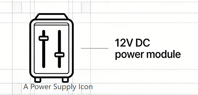
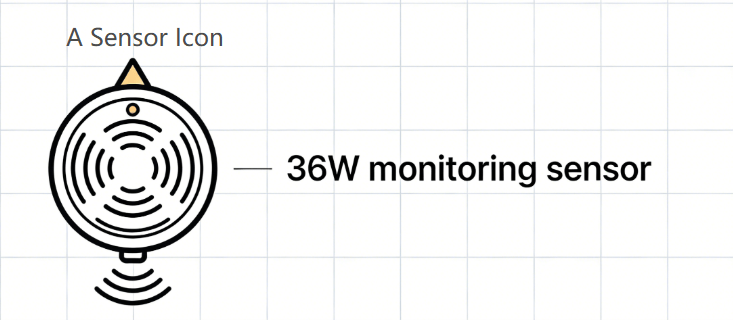
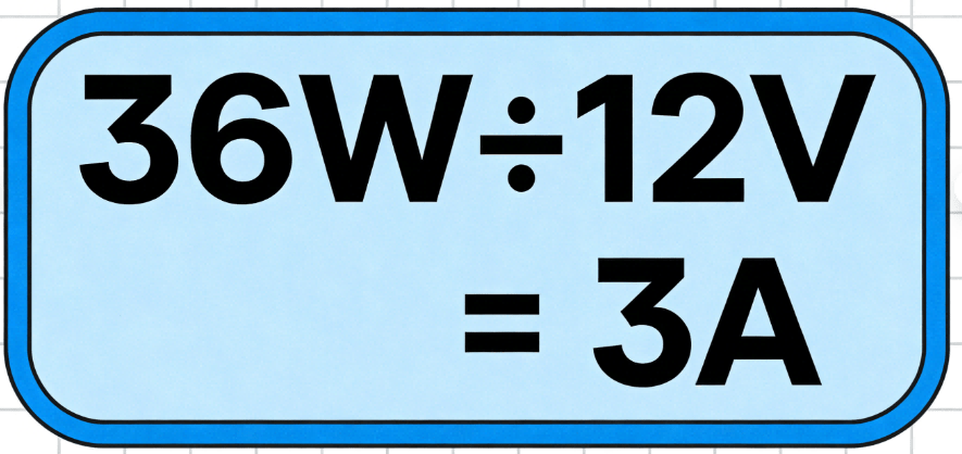
Suppose you’re designing a 12V DC patient monitor PCBA, and its main sensor consumes 36W of power. Here’s how to figure out amperage from watts:
Industrial PCBA (e.g., HVAC controls, factory robots) sometimes use AC power. For AC, the formula includes a
power factor (PF)—a measure of how efficiently current is used (typically 0.8 for most industrial equipment):
Amps (A) = Watts (W) ÷ (Volts (V) × Power Factor)
Example: A 220V AC industrial motor driver uses 100W. With a 0.8 PF:
Amps = 100W ÷ (220V × 0.8) ≈ 0.57A
Watts to Amps Calculators: Tools for Accurate PCBA Power Design
Manual calculations work for simple designs, but a watts to amps converter or wattage amps calculator reduces errors—especially for high-volume PCBA production.
- HCJMPCBA Custom Watt-Amp Calculator: Our free tool includes PCBA-specific features (DC/AC toggle, trace rating validation, and component compatibility checks).
- Digi-Key Watt-Amp Calculator: Ideal for quick component-focused calculations.
- IPC Trace Ampacity Calculator: Validates PCB trace width against amp requirements (critical for avoiding overheating).
- Forgetting to input voltage: The #1 error in PCBA design (e.g., using 220V instead of 12V leads to wildly incorrect amp calculations).
- Ignoring power factor: For AC PCBA, this can undercalculate amps by 20% or more.
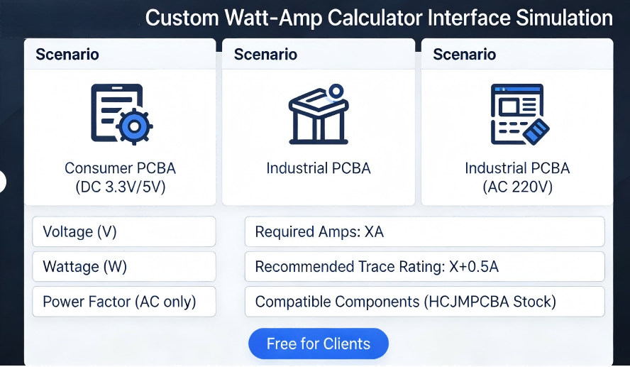
Hcjmpcba Custom Watt Amp Calculator Interface Simulation Diagram
Let’s apply watts to amps conversion to three distinct PCBA scenarios—each with HCJMPCBA’s tailored solutions:
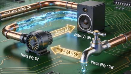
- Specs: 5V DC, 10W speaker + microcontroller
- Watts to amps calculation:
10W ÷ 5V = 2A
- HCJMPCBA’s Role: Select 2.5A-rated copper traces (adds a safety margin) and a 5V/2A power management IC (PMIC) to stabilize current.
- Specs: 24V DC, 48W motor driver
- Calculation:
48W ÷ 24V = 2A
- HCJMPCBA’s Role: Add thermal vias (small holes filled with copper) around the driver to dissipate heat from 2A current flow.
- Specs: 3.3V DC, 1.65W soil moisture sensor
- Calculation:
1.65W ÷ 3.3V = 0.5A
- HCJMPCBA’s Role: Validate low-power component compatibility (e.g., a 0.5A sensor with a 3.3V low-dropout regulator/LDO).
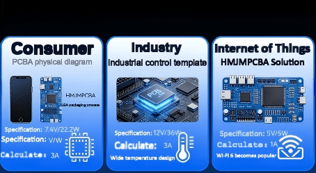
Pcba Scenario Case Infographic Hcjmpcba
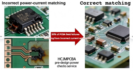
Even experienced engineers make watts to amps errors—but HCJMPCBA’s design-for-manufacturability (DFM) process catches them before production:
- Risk: Trace overheating, which can melt solder and disconnect components.
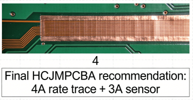
- HCJMPCBA’s Fix: Automated DFM checks that cross-reference trace width (per IPC-2221 standards) with calculated amps. For example, a 3A trace requires a 0.8mm width (for 1oz copper).
- Risk: A long trace can reduce voltage, which increases amps (per
A = W ÷ V), leading to unexpected component overload.
- HCJMPCBA’s Fix: Pre-production circuit simulations to map voltage drops; we add buffer capacitors to stabilize voltage for long traces.
- Risk: A component rated for 2A may fail under peak load (e.g., a 10W component drawing 2.2A for 10ms).
- HCJMPCBA’s Fix: Source components with 20%+ power tolerance (e.g., a 2.5A component for a 2A design) and test peak load in our lab.
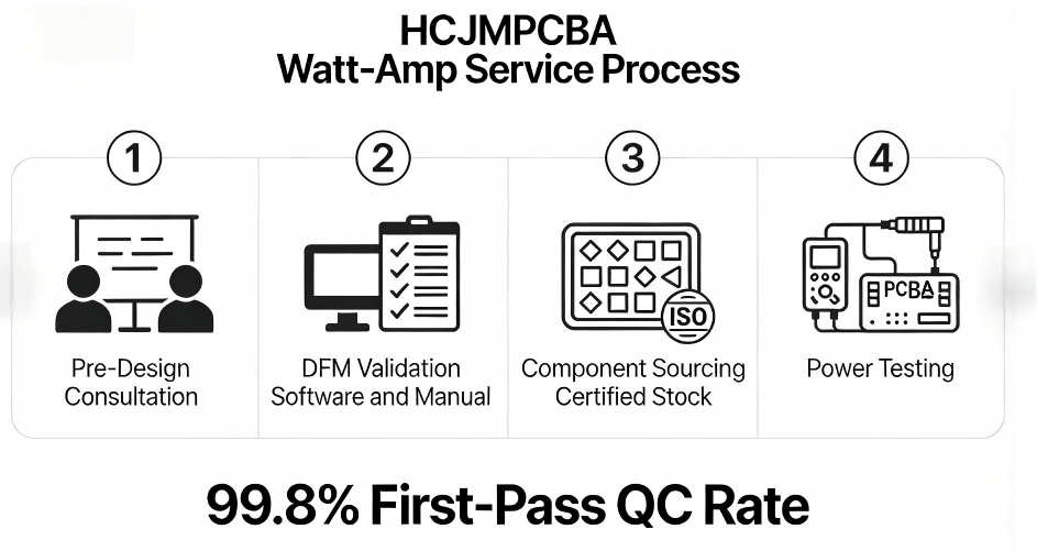
Hcjmpcba Watts to Amps Service Process
Our 15+ years of PCBA manufacturing experience means we don’t just calculate watts to amps—we integrate it into every step of production to eliminate risk:
We work with your engineering team to define optimal voltage/wattage specs, calculate amps from watts, and select components that align with your PCBA’s use case.
Our DFM software checks trace amp ratings, voltage drops, and component tolerances—then our engineers review every design to catch edge cases (e.g., peak load scenarios).
We source 100% genuine components (ISO 9001 certified) with verified watt/amp ratings—no counterfeits that fail under load.
Every PCBA batch undergoes power testing: we measure actual amps/watts to confirm alignment with design specs. Our 99.8% first-pass QC rate means fewer reworks and faster delivery.
“HCJMPCBA’s
watts to amps checks cut our consumer PCBA rework cost by 40%. Their DFM team caught a trace rating error that would have scrapped 5,000 units.”
— Senior Engineer, Global Consumer Electronics OEM
It depends on voltage: 1W ÷ 5V = 0.2A; 1W ÷ 12V ≈ 0.083A. This is critical for low-power IoT PCBA (e.g., 3.3V sensors drawing 0.3A = 1W).
Use Amps = Watts ÷ (Volts × Power Factor). Most industrial AC PCBA use a 0.8 power factor (e.g., 100W ÷ (220V × 0.8) ≈ 0.57A).
Watts to amps calculates current (A) from power (W); amps to watts calculates power (W) from current (A) (use W = A × V).
Watts to amps conversion isn’t just a math exercise—it’s the foundation of PCBA designs that perform consistently, avoid costly failures, and meet client expectations. Whether you’re designing a 5V consumer PCB or a 24V industrial system, calculating amps from watts correctly ensures your components, traces, and power supplies work in sync.
HCJMPCBA’s end-to-end power design support—from pre-design consultation to post-production testing—takes the guesswork out of watts to amps for PCB/PCBA. Our focus on IPC standards, certified components, and safety margins means your designs are reliable from prototype to mass production.