How to Use a Multimeter: The Complete Practical Guide for Engineers and Beginners
If you want to quickly understand how to use a multimeter, this guide explains the practical steps u
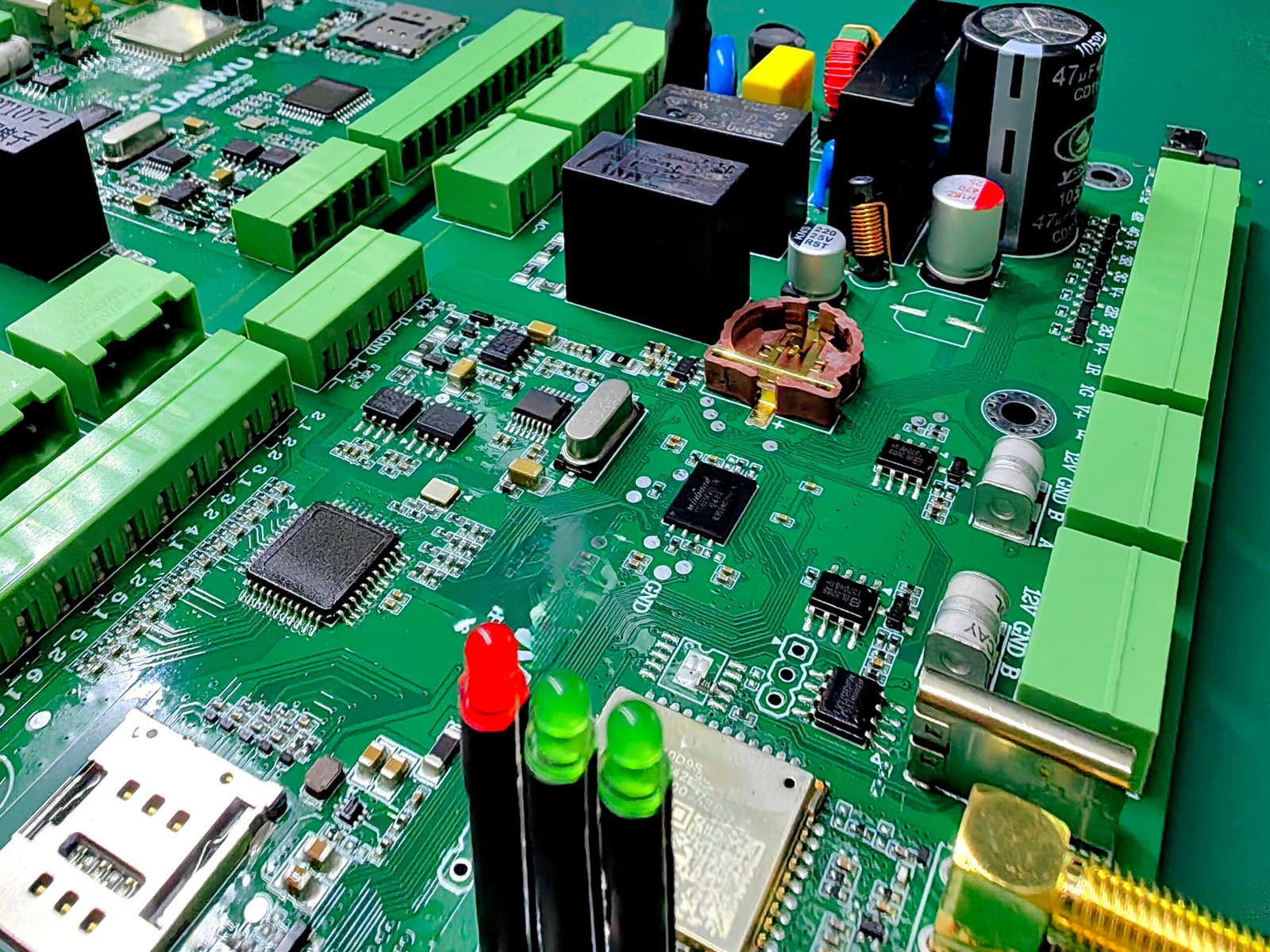
In modern electronics and printed circuit board assembly (PCBA), relays are ubiquitous control components that act as electrically operated switches, enabling low-power control circuits to manage higher-power loads safely and reliably. Whether in automotive control modules, industrial automation, HVAC systems, or household appliances, relays provide essential switching functionality and circuit isolation while protecting sensitive electronics and extending device longevity.
This guide breaks down what a relay is, what a relay does, and how relays work step by step — including electromechanical and solid-state types — and explains how HCJMPCBA tests and integrates relays in PCBA workflows to minimize defects and procurement risk.
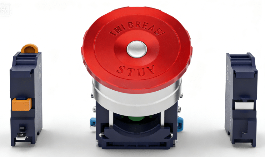
What Is A Relay Hcjmpcba
A relay is fundamentally an electrically operated switch that opens or closes contacts in one circuit based on a control signal from another circuit. Unlike a manual switch, a relay responds to electrical triggers without human interaction, making it ideal for automated control tasks in electronic systems.
Acts as a switch controlled by electricity rather than manual input. IBE Electronics
Allows low-power signals to control higher-power circuitry, enabling isolation and protection.
Provides galvanic isolation between control and load circuits, reducing noise and interference
Relays also extend the life of control electronics by handling high inrush currents and transient spikes that would otherwise damage delicate ICs or microcontrollers.
At the core of most relays is a coil, a movable armature, and one or more sets of contacts. When current flows through the coil, it generates a magnetic field that moves the armature, changing contact positions to either open or close a circuit. This action allows small control signals to manage much larger loads.
Coil Energizing: When a control voltage is applied to the relay’s coil, it generates a magnetic field.
Armature Activation: The magnetic field pulls the armature toward the coil, overcoming the return spring.
Contact Switching: The armature movement either closes normally open (NO) contacts or opens normally closed (NC) contacts, completing or interrupting the load circuit.
Release & Reset: When the coil voltage is removed, the spring returns the armature to its default position, reversing the contact states.
This configuration allows a tiny control current to switch much larger load currents without direct electrical connection between control and load circuits.
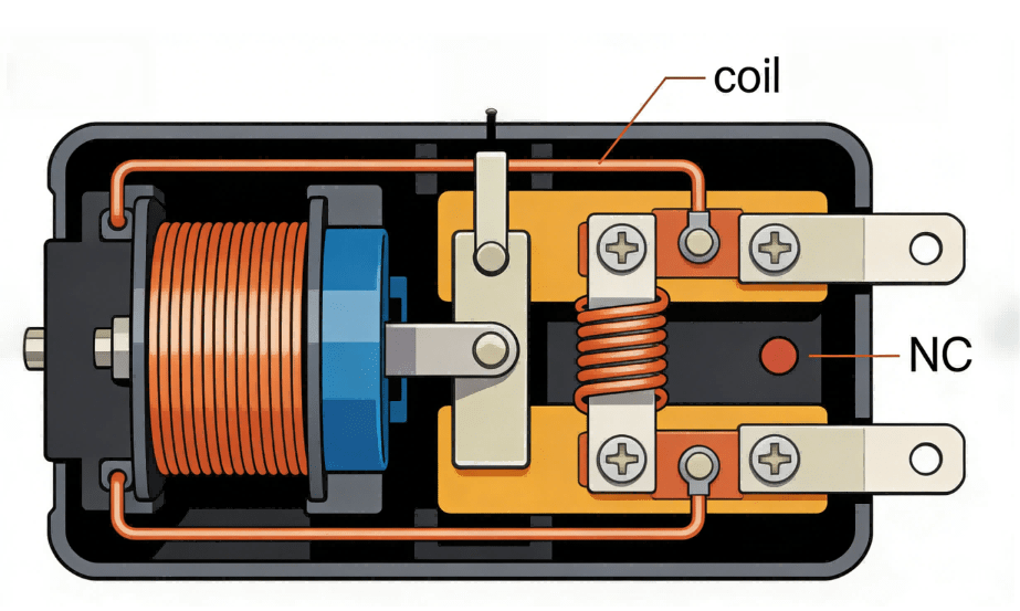
Internal Structure Of The Relay Hcjmpcba
Solid-state relays use semiconductor devices (like TRIACs, MOSFETs, or optocouplers) instead of moving parts to switch the load. They operate silently and with higher switching speeds, making them suitable when mechanical wear or arcing must be minimized.
Relays are named based on how many circuits they control and how the contacts switch:
SPST (Single-Pole Single-Throw): Basic on/off control
SPDT (Single-Pole Double-Throw): One input toggles between two outputs
DPDT (Double-Pole Double-Throw): Controls two independent circuits with dual throw capability
These forms allow flexible design options for PCBA control logic and multi-mode switching.
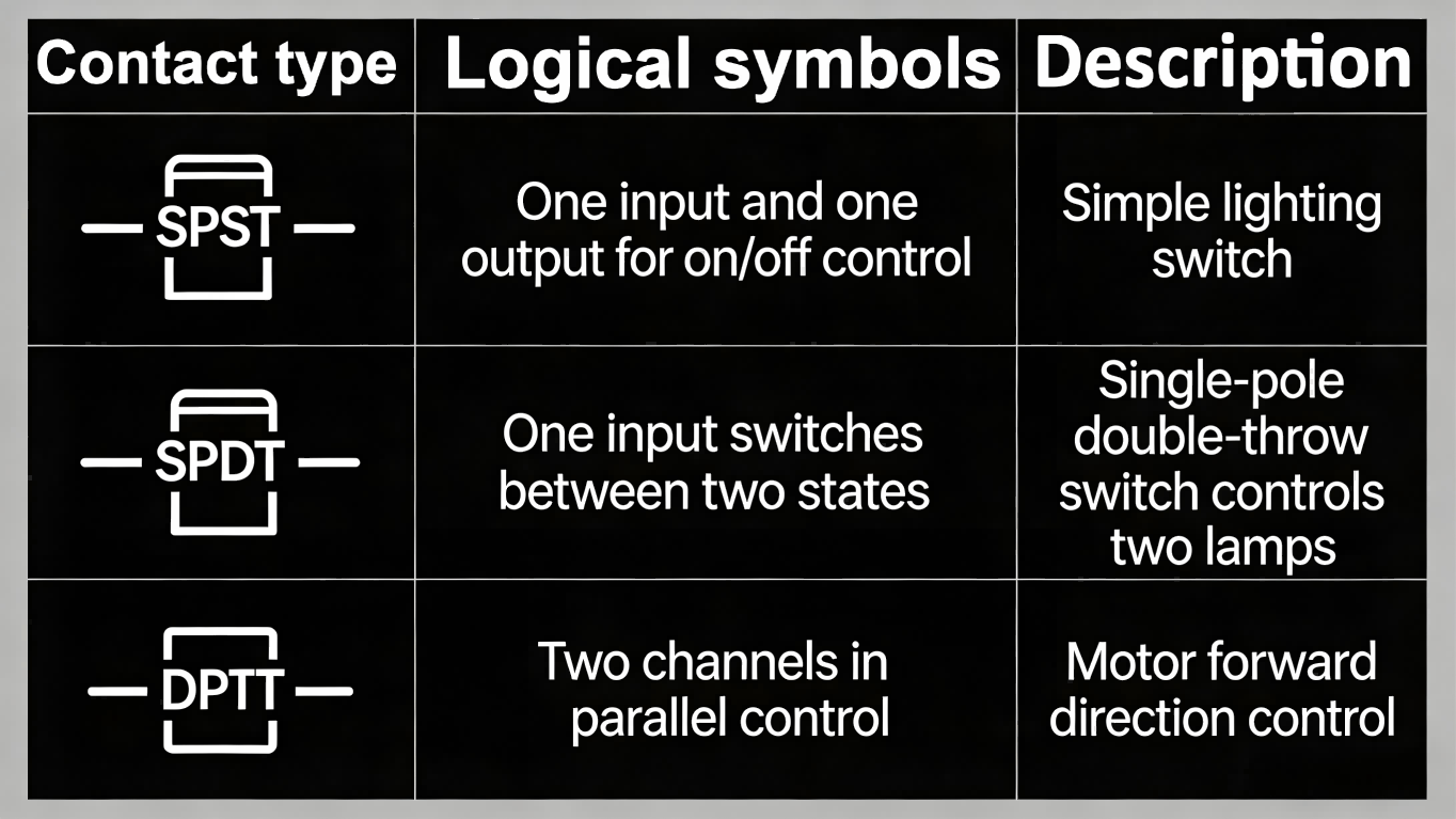
Spstvsspdtvsdpdt Hcjmpcba
Relays are essential in many practical applications because they allow control signals from microcontrollers, sensors, or other low-power circuitry to safely manage high-power components such as motors, heaters, lights, and solenoids without exposing the control side to large currents.
In automotive systems, relays are widely used to control starter motors, headlights, and cooling fans. A relay’s coil may be driven by a small voltage signal from an engine control unit (ECU) to switch a high current fuel pump circuit without high-current wiring running through the control module — improving safety and reducing wiring complexity.
Relays also act as protective devices in circuits, disconnecting power during an overload, fault condition, or emergency shut-down. Protective relays in power systems can detect issues like overcurrent, phase imbalance, or ground faults, triggering circuit isolation before damage occurs.
Correct relay selection and verification are critical steps in PCBA design. Testing ensures that relays not only meet design specifications but also function reliably over time.
Engineers typically measure:
Coil Resistance: Ensures the relay coil draws the expected current
Contact Resistance: Checks that contacts have low resistance when closed
Activation Response: Measures how fast the relay contacts change state under load
Specialized test fixtures or automated testers may be used to repeatedly operate relays and log performance over thermal cycles.
During PCB design, placements for test points near relay coils and contacts make it easier to diagnose issues during prototyping and mass production testing. Designing easy-access test points for signal tracing and probe attachments reduces debugging time and improves yield.
Common issues include:
Contact Arcing & Wear: Mechanical relays may arc under load, causing pitting and eventual failure.
Coil Burnout: Excessive voltage or thermal stress can degrade the coil.
Poor Solder Joints: Inadequate soldering can lead to intermittent contacts or open circuits.
At HCJMPCBA, we follow a structured testing and validation process:
Specification Review: Ensure relay voltage, current, and contact ratings match design requirements.
Component Sourcing Verification: Parts are sourced from authorized distributors to avoid counterfeit or substandard relays.
Functional Testing: Every relay is tested with controlled load conditions before assembly.
Thermal & Load Cycling: Relays are operated across temperature ranges to validate long-term reliability.
Documentation & Traceability: Test results are logged and linked to specific PCB batches.
These steps help reduce failures in the field and give PCBA customers greater confidence in product performance.
In a recent automotive control module project, HCJMPCBA engineers chose relays with robust ratings and tested them across environmental extremes. By validating contact resistance and coil activation under simulated vibration and thermal stress, the team reduced on-vehicle field failures by over 40% year-over-year — demonstrating how thoughtful relay selection and testing translate to real-world reliability.
When selecting a relay, consider:
Coil Voltage & Current Requirements
Contact Rating (AC/DC current handling capacity)
Switching Speed & Lifespan
Galvanic Isolation Needs
Avoid low-cost, unverified relays that lack datasheet traceability — as these often lead to field failures and warranty costs.
Understanding what does a relay do, relay definition, and how relays work is fundamental for reliable PCBA design and manufacturing. Whether controlling high loads, isolating circuits, or ensuring safety under fault conditions, relays remain indispensable in electrical and electronic systems.
By partnering with HCJMPCBA, OEM engineers and procurement teams gain access to rigorous relay testing, thoughtful PCB integration, and reliable sourcing — enabling products that perform as intended, every time.
If you want to quickly understand how to use a multimeter, this guide explains the practical steps u
Discover pcb board washer methods tailored for HCJMPCBA’s SMT‑built assemblies—from manual bru
Discover a custom pcb design framework in 10 strategic steps—covering cost estimation, layout best


