What Is a Blank PCB and Parts? Comprehensive Guide for Engineers and Buyers
Discover what a blank PCB and parts are—you'll learn about blank PCB board, bare printed circuit b
A printed circuit board (PCB)—also known as a printed wiring board—is the structural platform that mechanically supports and electrically connects electronic components using conductive copper traces laminated onto an insulating substrate. PCBs form the foundation of nearly all modern electronic devices, enabling reliable electrical connections between integrated circuits, resistors, capacitors, and other components.
1. A PCB board is the structural backbone of electronic products.
Every electronic device—from smartphones to industrial controllers—relies on circuit boards to connect electronic components.
2. PCB reliability depends heavily on design rules and materials.
Standards such as IPC-2221 define conductor spacing, via design, and layer stack-up requirements to ensure electrical reliability.
3. PCB design alone is not enough.
To manufacture a functional product, companies must convert PCB designs into PCBA (Printed Circuit Board Assembly) through controlled manufacturing processes, verification testing, and traceable production systems.
| Application | Recommended PCB Type | Key Reason |
|---|---|---|
| Consumer electronics | 4-layer FR4 PCB | Balanced cost and signal performance |
| Industrial control systems | 6–8 layer PCB | Improved EMI control |
| Automotive electronics | High-Tg PCB | Thermal resistance |
| RF / communication systems | Rogers or PTFE PCB | Signal integrity |
| Medical equipment | IPC Class 3 PCB | Maximum reliability |
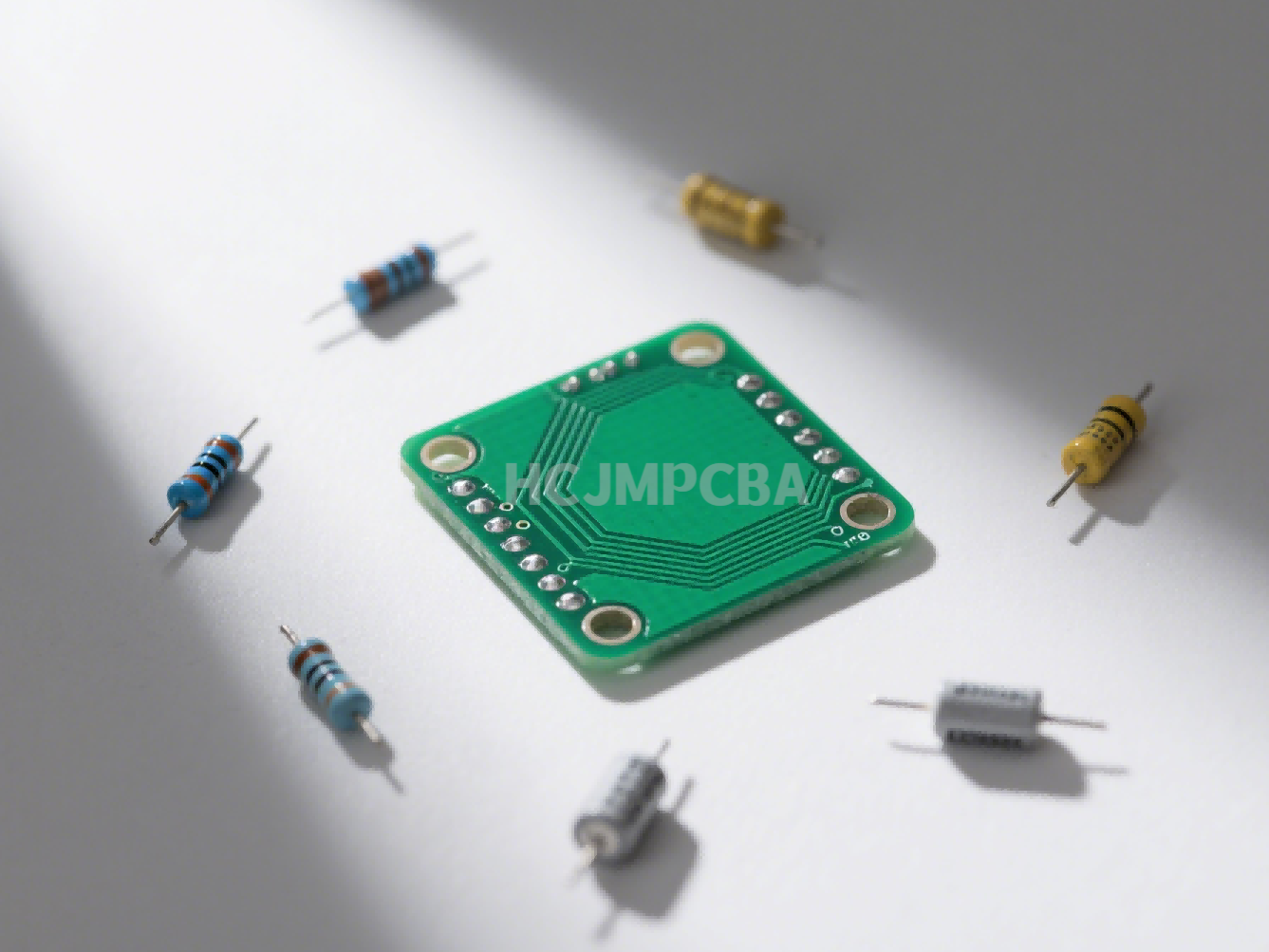
The PCB printed circuit board is the structural platform that connects electronic components to form functional electronic circuits.
Instead of manually wiring components together, engineers design copper traces directly onto a flat insulating board. These traces act as electrical pathways connecting components in a precise circuit layout.
A typical circuit board board structure includes:
Insulating substrate (FR4 or other dielectric)
Copper conductive traces
Solder mask protection
Silkscreen markings
Electronic components
Because of their high reliability and scalability, PCBs are used in nearly every electronic system today.
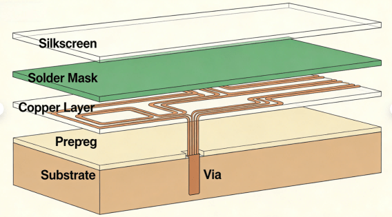
Pcb Board Structure Diagram Hcjmpcba
Understanding the parts of a PCB is essential for engineers designing electronics and buyers sourcing PCBA manufacturing.
Copper traces replace traditional wiring.
They conduct electrical signals between components.
Trace width and spacing are controlled according to IPC-2221 design rules.
Pads are exposed copper areas used for soldering components onto the board.
Types include:
Surface mount pads
Through-hole pads
Vias are metal-plated holes that connect electrical signals between different PCB layers.
Types include:
Through vias
Blind vias
Buried vias
Microvias (HDI PCB)
The solder mask is a protective coating applied to the PCB surface.
Functions:
Prevent solder bridges
Protect copper from oxidation
Improve assembly accuracy
Silkscreen provides identification information such as:
Component labels
Part numbers
Test points
Assembly marks
Typical printed circuit board components include:
| Component | Function |
|---|---|
| Resistor | Control current |
| Capacitor | Store energy |
| Inductor | Filter signals |
| Integrated Circuit | Process signals |
| Connector | Interface between systems |
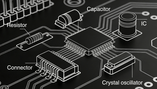
Pcb Components Identification Hcjmpcba
Another common question engineers ask is:
What are PCB boards made of?
A typical electronic printed circuit board contains several materials.
The substrate provides structural support and electrical insulation.
Common materials:
| Material | Application |
|---|---|
| FR-4 | Standard electronics |
| High-Tg FR4 | Automotive |
| Rogers | RF / microwave |
| Polyimide | Flexible PCB |
FR-4 glass-epoxy laminate is the most common PCB substrate material.
Copper layers carry electrical signals across the board.
Typical thickness:
1 oz copper
2 oz copper
Heavy copper designs
Prepreg layers bond multiple PCB layers together to form multilayer boards.
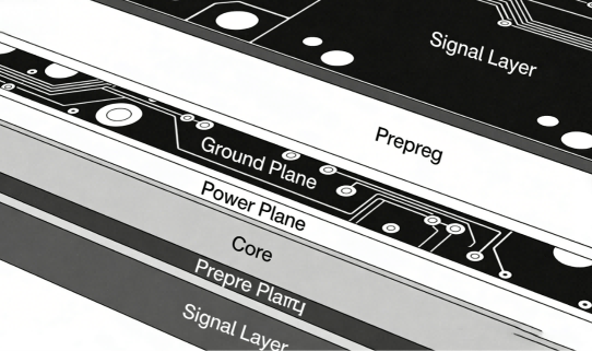
Multilayer Pcb Stackup Hcjmpcba
Electronic components are attached to PCB boards through two main assembly technologies.
SMT places components directly onto surface pads.
Advantages:
Higher density
Smaller boards
Automated manufacturing
Components are inserted through drilled holes.
Advantages:
Strong mechanical connection
Suitable for power components
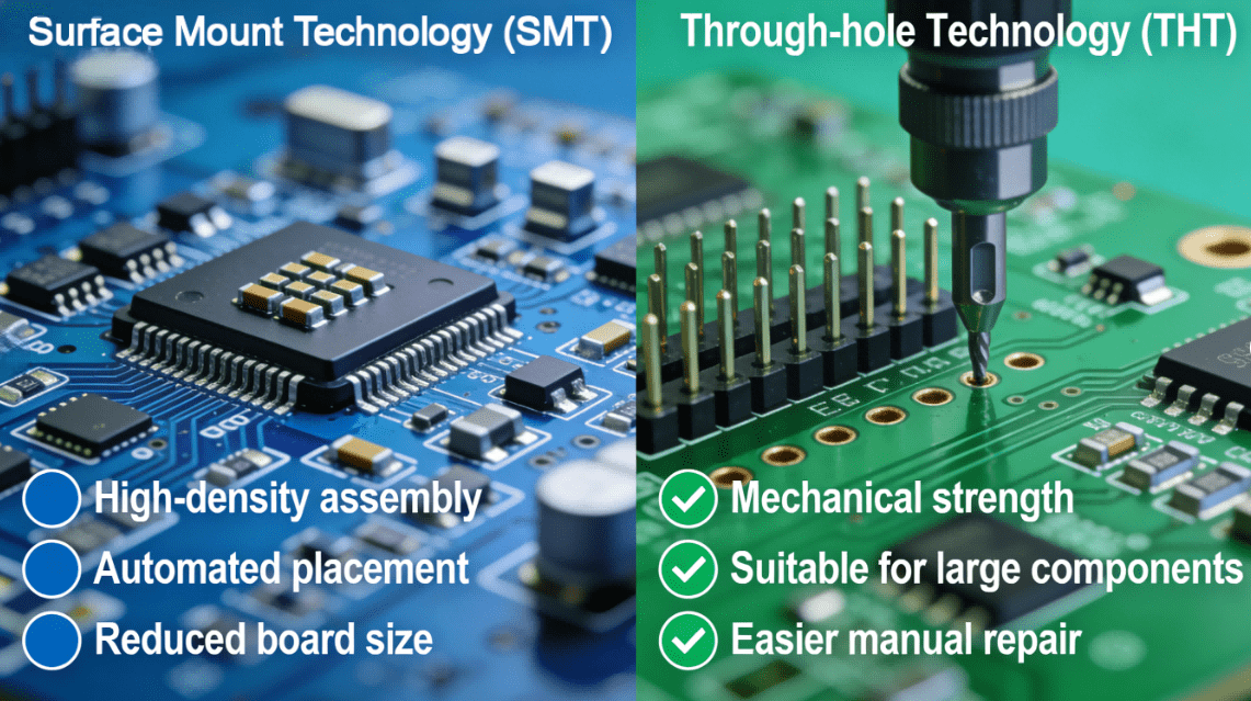
Smt Vs Through Hole Pcb Hcjmpcba
Designing a PCB requires a structured engineering workflow.
Engineers first create a schematic diagram representing the circuit logic.
Each electronic component must match a defined footprint in the PCB layout.
Stack-up design determines:
signal integrity
impedance control
EMI performance
Trace routing connects all components based on the schematic.
Engineers verify:
impedance matching
noise coupling
thermal effects
Design for Manufacturing ensures the PCB can be reliably produced.
Many electronics startups fail not because of design problems but because of manufacturing quality risks.
A reliable PCBA supplier should provide transparent production documentation and traceability.
| Document | Purpose |
|---|---|
| Method Number + Revision | Process control |
| Sample Plan | Quality inspection |
| Test Conditions | Verification criteria |
| Raw Data | Quality evidence |
| Traceability records | Product history |
| Level | Example |
|---|---|
| Lot traceability | PCB laminate batch |
| Batch traceability | Assembly production batch |
| Serial traceability | Individual board tracking |
| Verification Item | Evidence |
|---|---|
| Solder quality | IPC-A-610 inspection |
| PCB quality | IPC-A-600 |
| Functional test | test report |
| Electrical testing | ICT / FCT data |
| Traceability | lot / batch / serial |
Example requirement clause for procurement documents:
Supplier must provide full traceability records including PCB lot number,
component batch identification, and PCBA serial number.
All assemblies shall comply with IPC-A-610 acceptance standards
and include raw functional test data and process documentation.
1.Poor trace routing causing signal noise
2.Insufficient thermal design
3.Incorrect stack-up configuration
4.Ignoring EMI shielding
5.Lack of manufacturing tolerance consideration
Example: Industrial IoT Controller
Development process:
1 Prototype PCB fabrication
2 Functional validation
3 Engineering PCBA assembly
4 Reliability testing
5 Mass production PCBA
Manufacturers with strong engineering capabilities can significantly reduce product development risk.
To ensure supplier credibility, buyers should request:
process documentation
method revision history
inspection reports
raw test data
traceability reports
These documents provide verifiable evidence of production quality.
Q:What is a PCB board?
A:A PCB board is an insulating substrate with copper traces that connect electronic components to form functional circuits.
Q:What are PCB boards made of?
A:Most PCB boards use FR-4 glass-epoxy substrates with laminated copper layers and protective solder masks.
Q:What are the parts of a PCB?
A:Typical pcb board parts include copper traces, vias, pads, solder mask, silkscreen, and electronic components.
Q:What electronic components are on a circuit board?
A:Common circuit board electronic components include resistors, capacitors, integrated circuits, connectors, and sensors.
Q:What is the difference between PCB and PCBA?
A:PCB refers to the bare circuit board, while PCBA refers to the board after electronic components have been assembled and soldered onto it.
HCJMPCBA supports global OEM customers with:
full-process PCBA manufacturing
traceable production systems
engineering-driven manufacturing
international quality standards
The company provides transparent production documentation including method numbers, test conditions, and raw inspection data to ensure reliable electronics manufacturing.
Update triggers: standard revision changes / recurring questions / production checklist updates.
Discover what a blank PCB and parts are—you'll learn about blank PCB board, bare printed circuit b
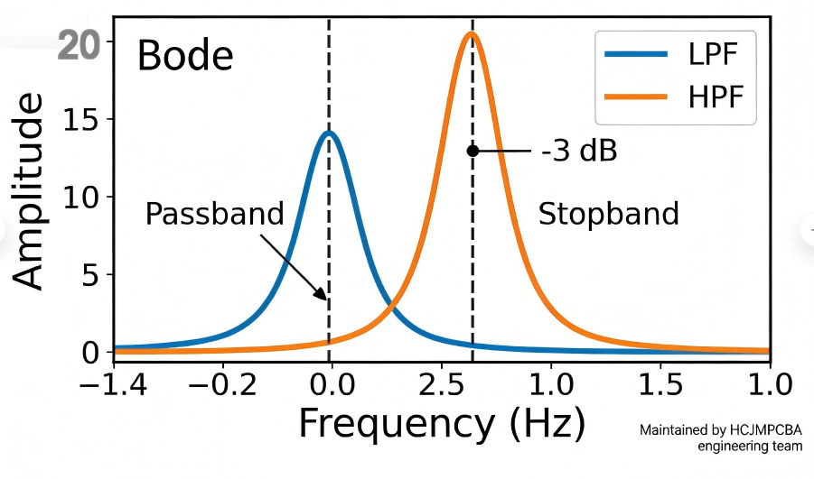
A low pass filter is a circuit that allows low-frequency signals to pass while attenuating higher-fr
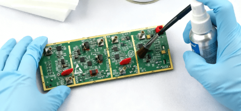
Cleaning flux and post-soldering residues is a key step in the PCBA manufacturing process. From SMT


