
How to Read the Resistor Color Code?
Learn how to read the resistor color code with our step-by-step guide. Decode 4-band and 5-band resi
Electric current is the flow of electric charge through a conductor, typically measured in amperes (A). In electronics and manufacturing of printed circuit board assemblies (PCBA), the ability to predict and control where current flows is critical for reliability, performance and safety. One principle that engineers must master is the current divider rule.
The term current divider refers to the scenario when a source current splits into two or more branches in a parallel network. The current division equation describes how the total current is shared between branches. Understanding the current divider formula, the current divider rule, and how to apply them helps ensure correct trace sizing, via sizing, thermal load balancing and proper distribution of current in parallel paths—a common scenario in modern PCBs and PCBA assemblies in medical, industrial control, new energy and consumer-electronics sectors.
In PCB/PCBA manufacture, multiple traces, vias or layers often share the same current-source path or load path. Without proper current-division design, one branch may carry excessive current, overheat or degrade prematurely, while another branch remains under-utilised. That’s why mastering “what is a current divider” and ensuring your manufacturing partner uses the right current division rule is a mark of professional design.
When several resistive (or otherwise impedance) branches are connected in parallel and share a common voltage, the current divider formula provides a shortcut method to calculate branch currents when the total current is known. ([turn0search1]turn0search1)
For two resistors R1R_1 and R2R_2 in parallel, with total current ITI_T flowing into the node, the branch current in R1R_1 (denoted IR1I_{R1}) can be expressed as:
IR1=IT×R2R1+R2\mathbf{I_{R1} = I_T \times \frac{R_2}{R_1 + R_2}}
and likewise for R2R_2:
IR2=IT×R1R1+R2\mathbf{I_{R2} = I_T \times \frac{R_1}{R_1 + R_2}}
You’ll note the inverse relationship: the branch with lower resistance draws a larger current because current splits in inverse proportion to resistances. ([turn0search0]turn0search0)
A more general expression is:
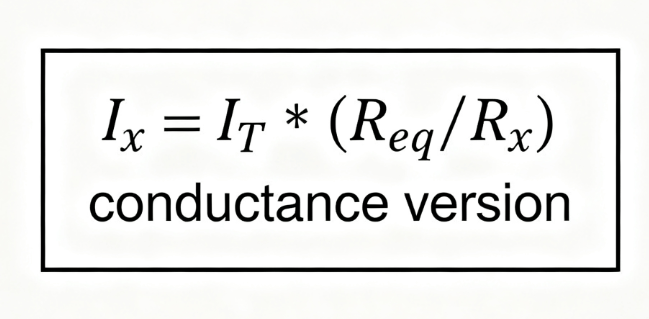
Ix=IT×ReqRx\mathbf{I_x = I_T \times \frac{R_{eq}}{R_x}}
where ReqR_{eq} is the equivalent resistance of the parallel network and RxR_x is the resistance of the branch in question. ([turn0search12]turn0search12)
You’ll also see the alternative formulation using conductances (G, the reciprocal of resistance):
Ix=IT×GxGTI_x = I_T \times \frac{G_x}{G_T}
which is particularly useful in high-speed PCBA design when impedances matter.
Suppose a PCB power plane supplies IT=10I_T = 10 A into two parallel trace segments of R1=2 ΩR_1 = 2\,\Omega and R2=8 ΩR_2 = 8\,\Omega. Equivalent resistance Req=1/(1/2+1/8)=1.6 ΩR_{eq} = 1 / (1/2 + 1/8) = 1.6\,\Omega. The current in branch 1 is:
IR1=10×1.62=8 AI_{R1} = 10 \times \frac{1.6}{2} = 8\,\text{A}
And branch 2 gets:
IR2=10×1.68=2 AI_{R2} = 10 \times \frac{1.6}{8} = 2\,\text{A}
This simple application of the current divider rule verifies that branch currents add to total current (8 A + 2 A = 10 A) and follow the inverse-resistance principle. For complex PCBA assemblies and multiple resistive/impedance paths, the same logic scales with more branches and even frequency-dependent impedance behaviour.
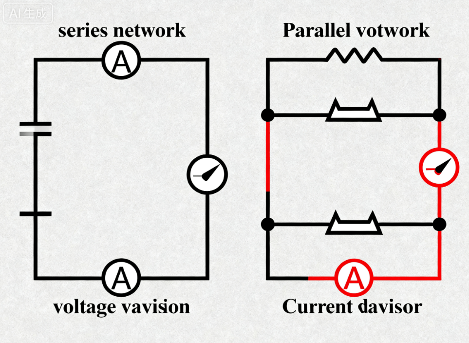
While the current divider rule governs how current splits in parallel networks, the voltage divider rule governs how voltage splits across series networks. It’s easy to confuse the two, but mixing them up can lead to major design errors in PCBA manufacturing. ([turn0search1]turn0search1)
Key differences:
Voltage Divider: Applies to components in series; same current flows through each element; voltage divides in proportion to component resistances.
Current Divider: Applies to components in parallel; same voltage across each branch; current divides in inverse proportion to resistances.
In PCB/PCBA design:
When two traces branch off a power plane (parallel), one should evaluate using the current divider formula (branch currents).
When two resistances in series drop voltage (e.g., reference network), one uses the voltage divider rule formula.
Use this distinction when evaluating your PCBA supplier’s datasheets or layout reviews. Asking “Which rule did you apply here?” can quickly reveal whether your manufacturer understands trace/branch current sharing and load balancing.
In modern manufacturing—whether for medical devices, industrial control systems, automotive electronics or new-energy solutions—PCB/PCBA often have complex parallel paths for current distribution, power sharing, redundant paths and high-reliability design. Understanding and applying the current divider rule makes the difference between a robust design and a board that overheats, drifts or fails prematurely.
Parallel traces or via arrays are common ways to split current in PCBA layouts: two tracks feed the same device, or multiple vias share a high-current path. If the resistances of those paths are not equal (or not compensated), one path may hog current leading to thermal hotspots. By applying the current division equation early, designers ensure equal current splitting, proper sizing and improved reliability.
In power-supply modules or battery management boards, multiple parallel MOSFETs or shunt resistors share current. For designers and procurement in OEMs, asking for the current divider rule calculator or demonstrable current-sharing data is crucial. Long-tail keywords like “current division rule calculator”, “parallel circuit current divider” apply here.
Although the classic current divider rule deals with steady DC/low-frequency current, its IEEE counterparts in high-speed PCBs include parallel impedance paths where currents split at high frequencies. Incorrect branching may degrade signal integrity or cause EMI issues. Ensuring your PCB/PCBA vendor knows “how to find current in a parallel circuit” helps avoid these pitfalls.
Medical devices: Redundant power paths for safety, current sharing in critical subsystems.
Industrial control: Multiple parallel sensors, actuators drawing from same bus; branch heating must be controlled.
Renewable energy: Solar inverters, battery packs with parallel strings; current division ensures longevity.
Automotive/e-mobility: High current bus bars, multicore PCBs needing equal splitting, compliance with strict reliability standards.
In all cases, using the current divider rule is not optional—it’s fundamental for OEMs and procurement to specify and verify.
Here’s a practical workflow for engineers, buyers and procurement professionals working with a PCBA manufacturing partner like HCJMPCBA.
Identify the total current (I_T) entering the parallel network.
This data should come from your system-level specification or current-budget sheet.
Calculate or determine the equivalent resistance (R_eq) of the parallel branch network.
If traces/vias are equal, consider resistance; if impedances differ at high-speed, include impedance modelling.
Select the branch whose current you need to compute (R_x or G_x).
Apply the formula:
Ix=IT×ReqRxI_x = I_T \times \frac{R_{eq}}{R_x}
or
Ix=IT×GxGTI_x = I_T \times \frac{G_x}{G_T}
Use consistent units; double-check conductance form if relevant.
Verify conservation of current: sum of all branch currents = total current. This aligns with Kirchhoff’s Current Law (KCL). ([turn0search11]turn0search11)
Include in procurement/contract specification: ask your PCBA supplier for the current division calculation sheet or evidence of current balancing in the design review.
Monitor branch currents in real board test: thermographic imaging, current sensing, via temperature measurement.
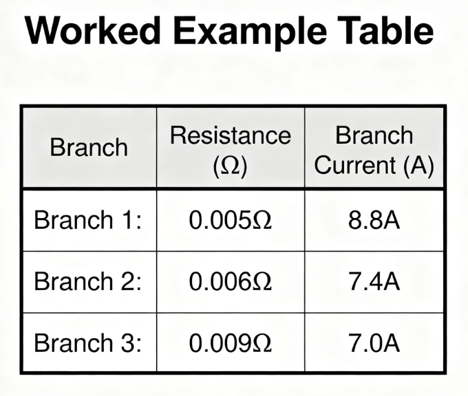
Suppose a power plane supplies 24 A into three parallel via/trace paths each aimed to share the load equally. Each path is designed for ≈8 A. If actual resistances differ (e.g., 0.005 Ω, 0.006 Ω, 0.009 Ω), compute branch currents:
ReqR_{eq} = 1 / (1/0.005 + 1/0.006 + 1/0.009) ≈ 0.00183 Ω
I1=24×0.00183/0.005≈8.8AI_1 = 24 × 0.00183 / 0.005 ≈ 8.8 A
I2≈7.4AI_2 ≈ 7.4 A
I3≈7.0AI_3 ≈ 7.0 A
Procurement should require the vendor to balance the resistances to within acceptable tolerance or add thermal mitigation for the higher-load branch. Keywords: “current division 3 resistors”, “series and parallel circuits equations”.
Here are frequent errors seen in PCB/PCBA manufacturing that engineers or procurement teams must avoid:
Mistake 1: Assuming equal current share solely because traces look symmetrical. However, differences in trace width, length, via count or copper thickness create uneven resistances → branch current imbalance.
Mistake 2: Applying the voltage divider rule in a parallel network (wrong rule for wrong context) — confusion between series vs parallel rules. (“voltage divider current divider” mix-up)
Mistake 3: Neglecting temperature rise, copper thickness variation, via thermal relief or PCB layer impedance which changes branch resistance under load.
Mistake 4: Not verifying the sum of branch currents equals total current; shunt paths or hidden resistances overlooked.
Mistake 5: Ignoring high-frequency effects (skin effect, impedance, inductance) that alter parallel current sharing in high-speed / power-electronics PCBs.
By asking your vendor for demonstration of the current divider rule calculator or simulation/report, you gain assurance of their design maturity. Keywords: “current divider example”, “current divider rule for the series parallel circuit”.
What is the current divider rule?
The current divider rule states that in a parallel circuit, the current splits into branches in inverse proportion to the resistances of the branches. If one branch has half the resistance of another, it will draw twice the current. The current divider formula gives a direct calculation method for branch currents given the total current.
How do I calculate current in a parallel circuit with three resistors?
First compute the equivalent resistance Req=1/(1/R1+1/R2+1/R3)R_{eq} = 1 / (1/R_1 + 1/R_2 + 1/R_3). Then for branch 1: I1=IT×(Req/R1)I_1 = I_T × (R_{eq} / R_1). Repeat similarly for other branches. Ensure I1+I2+I3=ITI_1 + I_2 + I_3 = I_T.
What is the current formula vs voltage formula?
For current division: Ix=IT×(Req/Rx)I_x = I_T × (R_{eq}/R_x) or IT×(Gx/GT)I_T × (G_x/G_T). For voltage division (series): Vx=VT×(Rx/RT)V_x = V_T × (R_x / R_T). Remember: voltage divider uses numerator = R_x, current divider uses numerator = R_eq (or denominator flip).
How do I apply the current divider rule in PCB/PCBA design?
In your PCB layout or PCBA design, identify branches (traces, via arrays, power paths) that are in parallel. Estimate or measure their resistances/impedances. Use the current division equation to calculate branch currents. Then specify to your OEM partner correct trace/via sizing to achieve desired current sharing, avoid thermal hotspots and ensure reliability across applications (medical, industrial, new energy etc.).
In summary: mastering the current divider rule is essential for modern PCB and PCBA design. From the current divider formula to practical application in parallel circuits, you now understand how current splits, how to compute it, and how it directly affects your manufacturing outcomes. Whether you are evaluating a PCBA supply partner or reviewing layout specs, ask explicitly for current-division calculations, branch-current balancing, and simulation results.
By specifying the current divider rule, you demand higher-precision, better reliability and optimum performance. For your next OEM project, look for a manufacturing partner who treats current division as a design requirement—not an afterthought.
To learn more about our PCBA services, please contact Guangzhou Huachuang Precision Technology.
Learn how to read the resistor color code with our step-by-step guide. Decode 4-band and 5-band resi
An LED PCB is a specialized printed circuit board designed for LED applications, delivering electric
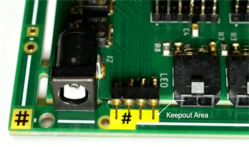
A keepout on a PCB is a software-enforced exclusion zone that prevents copper, vias, or components i


