What Is a Blank PCB and Parts? Comprehensive Guide for Engineers and Buyers
Discover what a blank PCB and parts are—you'll learn about blank PCB board, bare printed circuit b
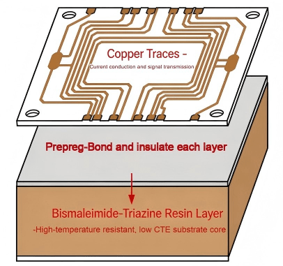
Bismaleimide-Triazine (BT) is a high-performance thermosetting resin system widely used as a substrate material for advanced printed circuit boards.
The polymer structure combines bismaleimide molecules, which provide mechanical rigidity and high thermal resistance, with triazine rings derived from cyanate ester chemistry, which contribute excellent electrical insulation and low dielectric loss.
Because of this molecular architecture, Bismaleimide-Triazine PCB substrates exhibit higher glass transition temperatures, lower moisture absorption, and improved dimensional stability compared with conventional FR-4 laminates.
These characteristics make BT substrates a preferred solution for semiconductor packaging, high-frequency communication modules, and automotive electronics.
Technical Snapshot
Bismaleimide-Triazine (BT) PCB is a high-performance laminate material used in advanced electronics manufacturing. The substrate is formed from a copolymer system combining bismaleimide molecules and cyanate ester resin, producing a thermoset polymer network with high thermal stability, low dielectric loss, and excellent dimensional stability for semiconductor packaging and high-frequency circuits.
From a materials science perspective, Bismaleimide-Triazine resin is a cross-linked thermoset polymer system formed through copolymerization between bismaleimide monomers and cyanate ester groups.
The curing reaction forms a three-dimensional network structure in which triazine rings are embedded within a rigid polymer backbone.
This structure produces a synergistic effect:
Bismaleimide groups contribute high temperature stability and mechanical strength.
Triazine rings improve dielectric performance and insulation resistance.
The cross-linked network enhances dimensional stability and chemical resistance.
The synergistic effect of the triazine ring and bismaleimide molecules results in a substrate material capable of maintaining electrical integrity under high thermal and environmental stress.
For modern electronic products operating at high frequencies and high power densities, this combination is essential for maintaining signal integrity and preventing substrate degradation.
Simple Bismaleimide Triazine Bt Pcb Structure Diagram
The fundamental chemistry of Bismaleimide-Triazine resin involves the reaction between two key molecular groups:
Bismaleimide compounds contain reactive double bonds that form stable cross-linked networks during polymerization.
These molecular structures provide:
high thermal stability
mechanical rigidity
strong adhesion to reinforcement fibers
Cyanate ester resins polymerize into triazine ring structures during curing. These aromatic rings provide:
excellent dielectric properties
low moisture absorption
improved insulation resistance
When combined, these materials create a hybrid polymer matrix that outperforms many traditional PCB laminates in both thermal and electrical performance.
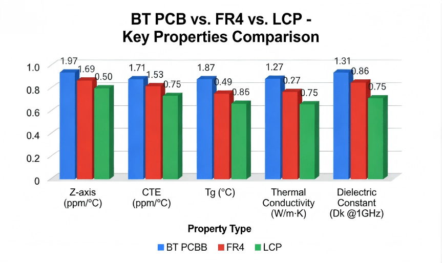
Compared with standard FR-4 materials, BT PCB substrates provide significantly improved electrical and thermal performance.
| Property | Bismaleimide-Triazine (BT) | FR-4 |
|---|---|---|
| Glass Transition Temperature (Tg) | 180–240°C | 130–170°C |
| Dielectric Constant (Dk) | 3.3–3.8 | 4.2–4.8 |
| Dissipation Factor (Df) | 0.003–0.006 | 0.015 |
| Moisture Absorption | <0.1% | ~0.3% |
| Dimensional Stability | Excellent | Moderate |
The most significant advantage of BT resin is its extremely low moisture absorption, which helps prevent delamination and blistering during solder reflow processes.
For high-density packaging technologies such as BGA and CSP substrates, this property is particularly critical.
Bt Pcb Vs. Other Substrates
In high-performance electronics, several advanced substrate materials are commonly used.
A comparison helps explain where BT resin PCBs fit within the broader materials landscape.
| Material Property | Bismaleimide-Triazine (BT) | Polyimide (PI) | Cyanate Ester |
|---|---|---|---|
| Glass Transition Temperature | 180°C – 240°C | 250°C+ | 220°C – 260°C |
| Moisture Absorption | <0.1% | 0.8% – 1.2% | ~0.2% |
| Dielectric Constant | ~3.4 | ~3.2 | ~3.0 |
| Processability | Excellent | Complex | Moderate |
| Cost Efficiency | High | Lower | Moderate |
Engineering Insight
Compared with conventional FR-4 laminates, Bismaleimide-Triazine substrates offer significantly lower moisture absorption and improved thermal stability. These characteristics help prevent delamination and warpage during solder reflow processes, making BT resin a preferred substrate material for high-density IC packaging and high-frequency electronic modules.
While polyimide substrates provide higher temperature tolerance, their moisture absorption can lead to reliability challenges during reflow processes.
BT resin substrates provide a balanced combination of thermal stability, electrical performance, and manufacturability, making them highly suitable for semiconductor packaging applications.
One of the most important applications of BT PCB technology is in IC substrate manufacturing.
Modern semiconductor packages require substrates capable of supporting:
extremely fine pitch interconnects
high signal integrity
thermal cycling resistance
dimensional stability during packaging processes
BT resin laminates provide the necessary characteristics for these environments.
In BGA (Ball Grid Array) substrates, the stability of the dielectric material directly affects signal transmission and package reliability.
Because BT materials exhibit low dielectric loss and low moisture absorption, they help maintain signal quality while reducing the risk of substrate warpage.
As a result, many semiconductor manufacturers use Bismaleimide-Triazine substrates as the foundation for IC package substrates.
Applications And Advantages Of Bt Pcb In Different Industries1
Due to their high reliability and excellent electrical performance, BT PCBs are widely used across multiple advanced electronics industries.
BT resin laminates are commonly used for BGA and CSP packaging substrates, where fine pitch routing and dimensional stability are required.
High-frequency RF modules benefit from the low dielectric loss and stable electrical properties of BT materials.
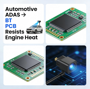
Electronic control units (ECUs) operating in harsh environments rely on thermally stable PCB substrates to maintain long-term reliability.
BT substrates help dissipate heat and maintain stable electrical performance in high-brightness lighting systems.
Industry Context
Bismaleimide-Triazine PCBs are widely used in semiconductor substrates, RF communication modules, and automotive control systems. Their stable dielectric performance and resistance to thermal cycling allow these materials to maintain signal integrity and mechanical reliability in demanding electronic environments.

Applications And Advantages Of Bt Pcb In Different Industries2
From a manufacturing perspective, the performance of BT PCB substrates depends not only on material properties but also on precise lamination and curing processes.
At HCJMPCBA, BT laminate processing follows controlled procedures designed to ensure consistent polymerization and dimensional stability.
The BT-L-04 lamination protocol defines several key parameters:
The curing cycle must follow a carefully controlled temperature ramp to achieve optimal polymer cross-linking.
During lamination, the viscosity of the BT resin must remain within specific limits to ensure uniform glass fiber wetting.
Uniform pressure ensures proper bonding between copper layers and dielectric substrates.
Boards produced using BT substrates are validated through thermal reflow simulations to verify resistance to delamination and warpage.
These manufacturing controls ensure that every BT PCB assembly maintains consistent performance during high-temperature assembly processes.
Applications And Advantages Of Bt Pcb In Different Industries3
High-performance PCB laminates are typically classified according to IPC-4101 standards, which define material requirements for rigid printed circuit board substrates.
Bismaleimide-Triazine laminates often correspond to material categories within the IPC-4101 specification related to high-temperature thermosetting resins.
Commercial laminate suppliers such as Mitsubishi Gas Chemical (MGC) provide BT resin systems used in advanced electronic substrates.
These material systems are widely adopted within semiconductor packaging and high-frequency electronics manufacturing.
Applications And Advantages Of Bt Pcb In Different Industries4
Q:What is Bismaleimide-Triazine PCB?
A:A Bismaleimide-Triazine PCB is a printed circuit board that uses BT resin as the dielectric substrate material. This resin combines bismaleimide and cyanate ester chemistry to deliver high thermal stability and low dielectric loss.
Q:Why is BT resin used for BGA substrates?
A:BT resin provides excellent dimensional stability and low moisture absorption, which helps prevent substrate deformation during solder reflow processes.
Q:Is BT PCB better than FR-4?
A:For high-performance electronics applications, BT substrates offer superior thermal resistance, lower dielectric loss, and improved reliability compared with standard FR-4 materials.
Q:What industries use BT PCB technology?
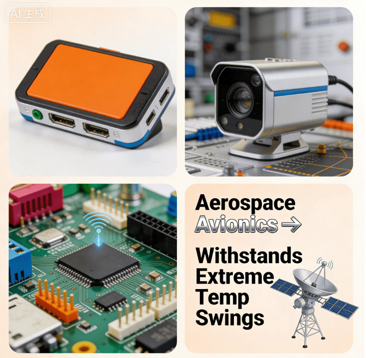
A:BT PCBs are commonly used in semiconductor packaging, telecommunications equipment, automotive electronics, and high-frequency RF systems.
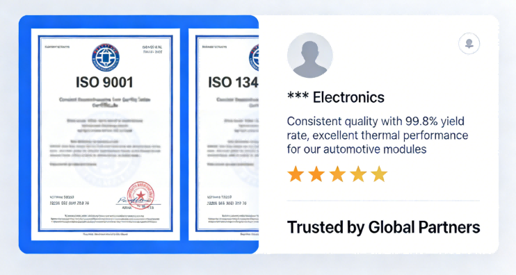
Product Quality And Market Feedback
Their hybrid polymer structure provides a balance of thermal stability, electrical performance, and manufacturability that is difficult to achieve with traditional PCB laminate materials.
As electronic devices continue to demand higher signal integrity and greater thermal tolerance, BT resin substrates will remain an essential component of advanced semiconductor packaging and high-performance electronic systems.
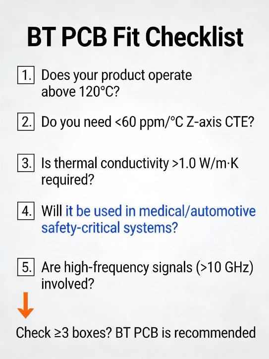
Bt Pcb Applicability Checklist
Discover what a blank PCB and parts are—you'll learn about blank PCB board, bare printed circuit b
For PCB/PCBA OEM engineers, procurement decision-makers, and cross-industry buyers, every component
Discover what is an ICT tester and how in-circuit testing (ICT) ensures PCB/PCBA quality with fast,