7 Critical FR4 ANSI Plate Selection Rules: When to Upgrade to High-Tg or Low-Loss Laminates for Reliable PCBA Production
Learn how to select the right FR4 ANSI plate for PCB projects in this engineering guide. Understand
The safest approach to how to discharge a capacitor is simple: power off → confirm isolation → measure voltage → discharge through a controlled path (usually a resistor or discharge tool) → verify with a multimeter → re-verify after a short wait. Direct shorting (for example, discharging a capacitor with a screwdriver) can create sparks, damage pads, and produce unsafe current spikes, so a controlled discharge is preferred in most professional workflows.
Capacitors are everywhere in electronic circuit boards: power supplies, motor drives, audio amplifiers, chargers, LED lighting, industrial controllers, and “everyday” devices like monitors and appliances. Many people learn how do you discharge a capacitor after a surprise: a snap, a spark, a burnt trace, or a painful shock even after the device was unplugged.
For PCB and PCBA teams, the consequences are bigger than discomfort. A careless capacitor discharge can:
Injure technicians
Destroy sensitive components
Carbonize PCB material around pads
Trigger intermittent failures that are hard to debug
Increase rework cycles and delay delivery
This article is written for practical use—engineers, technicians, and procurement teams who want a clear, repeatable method and verification steps. It explains what a capacitor does on a circuit board and then shows how to safely discharge a capacitor using several methods, including a multimeter-centered workflow.
A capacitor stores electrical energy in an electric field. In simple terms, it’s like a small “energy buffer tank” that can release energy quickly when the circuit needs it.
On pc boards and electronics circuit boards, capacitors typically serve these roles:
Power smoothing and ripple reduction: stabilize voltage rails
Decoupling and noise control: keep digital and analog circuits stable
Timing and filtering: shape signals and control response
Energy storage: support transient loads (motors, radios, power bursts)
In engineering terms, a capacitor’s behavior depends on capacitance (F), voltage rating (V), equivalent series resistance (ESR), leakage, and frequency response. That’s why one “looks similar” capacitor can behave very differently under load.
When a device is powered down, capacitors don’t instantly become safe. Charge can remain because:
The capacitor is isolated from a discharge path (no bleed resistor)
The circuit is open or disconnected
The load is too small to drain energy quickly
Some capacitors show “dielectric absorption,” where voltage can rebound slightly after discharge
That is why safe practice is never “assume it’s empty.” Measure, discharge, verify, and re-verify.
The proper way to discharge a capacitor is to begin with power isolation and confirmation. A safe checklist looks like this:
Turn off the device and unplug it
If it has a battery, disconnect the battery (or isolate it through the designed service procedure)
Press the power button (if applicable) to help drain low-voltage rails
Wait 1–5 minutes to allow any built-in bleed resistors to work
Prepare a clean workspace and keep your hands away from exposed conductors
Even “moderate” capacitors can deliver high peak currents. Basic protective habits reduce risk:
Use insulated gloves when appropriate
Wear eye protection (sparks and debris are real)
Use tools with insulated handles
Use probes with protective sleeves so only the tip is exposed
Keep one hand away when working on higher-voltage systems (reduces path through the chest)
If you’re unsure about voltage level or equipment category, treat it as high risk and escalate.
A practical kit for capacitor discharge includes:
Multimeter (with probes in good condition)
High-value power resistors (or a dedicated discharge tool)
Insulated leads and alligator clips
Needle-nose pliers with insulation
Optional: clamp meter (for current observation) and insulated mat
A capacitor discharging tool is designed to safely route energy through a controlled path (often a resistor network) and may include insulated probes and indicator lights. It reduces the temptation to “just short it,” and it reduces peak current spikes.
This is one of the easiest ways to make discharge a capacitor safely repeatable across a team.
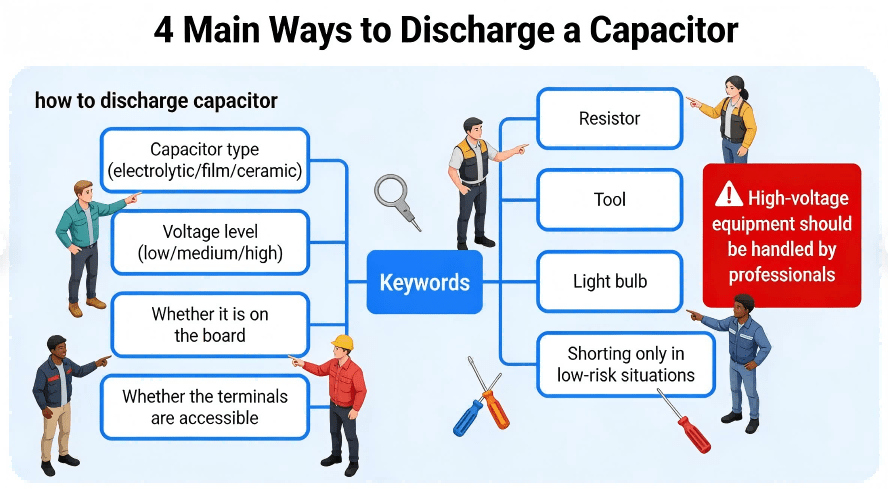
Use this quick guide before you choose how to discharge capacitor safely:
Low-voltage small capacitors (typical low-power boards): resistor discharge or discharge tool
Moderate-voltage power supply capacitors: resistor discharge + multimeter verification
High-voltage equipment (CRT, large drives, microwave oven): professional procedure, controlled discharge tool, strict verification
Hard-to-reach terminals / cramped PCB: alligator clips + resistor (avoid slips)
If unsure: treat as high-voltage and proceed cautiously
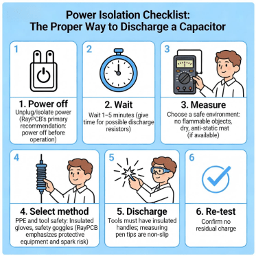
How To Discharge A Capacitor 6 Item Safety Checklist Before Discharging Diagram
Each method below follows the same professional pattern: Applicability → Tools → Steps → Verification → Notes.
Applicability: Most common and safest for general electronics work
Tools: Power resistor(s), insulated leads, multimeter
Steps (controlled discharge):
1.Measure capacitor voltage (DC volts mode). Record the value.
2.Attach insulated leads/alligator clips to the resistor first (avoid fumbling near live terminals).
3.Place the resistor across the capacitor terminals (or across the accessible points tied to those terminals).
4.Hold the connection until voltage drops near zero. Time depends on capacitance and resistor value.
5.Remove the resistor connection.
6.Re-measure voltage to confirm it is near zero.
Verification: Use a multimeter to verify voltage is near zero. Wait 1–2 minutes and measure again to confirm it does not rebound.
Notes:
Resistor discharge avoids large current spikes and reduces risk of arc damage. It’s generally the most responsible “default” answer to how can I safely discharge capacitor in PCB repair.
Many people search “how to discharge a capacitor with a multimeter” or “how to discharge capacitor with multimeter.” The most professional answer is: the multimeter is for measurement and verification, while the discharge is performed through a controlled path (resistor or discharge tool).
Applicability: Any situation where you must prove the capacitor is safe
Tools: Multimeter + resistor/discharge tool
Steps:
1.Set multimeter to DC voltage and measure the capacitor terminals.
2.If voltage is present, discharge using Method 1 (resistor) or a discharge tool.
3.Measure again immediately after discharge.
4.Wait briefly, then measure again (re-verify).
5.Only proceed with handling when readings remain near zero.
Why this matters: This workflow produces a measurement trail—useful in labs, repair benches, and production-quality processes.
A light bulb can act like a resistive load and provide a visual indicator that energy is being released.
Applicability: Some field setups where a bulb fixture is available and properly insulated
Tools: Suitable bulb + safe insulated wiring + multimeter
Steps:
1.Confirm isolation and measure voltage.
2.Connect the bulb as a controlled load across the capacitor terminals.
3.Observe the bulb response (if it lights, energy is flowing).
4.Keep connected until it dims/turns off, then verify with a multimeter.
Re-verify after a short wait.
Verification: Always verify with a multimeter even if the bulb goes dark.
Notes: This method can be useful, but it requires disciplined insulation and wiring to avoid accidental contact.
Search queries like “discharging a capacitor with a screwdriver” and “the proper way to discharge a capacitor is to…” show how common this idea is. In professional environments, direct shorting is generally treated as a last-resort method for specific situations—and only with appropriate insulation and awareness of consequences.
Why it’s risky:
High peak current can damage capacitor terminals
Sparks can burn pads and traces on a printed circuit board
The screwdriver can weld to terminals or cause metal splatter
It can create electromagnetic stress for nearby components
If someone insists on a shorting approach:
It should be limited to low-energy cases with proper insulation and protective equipment—yet in most PCB repair and assembly settings, resistor discharge is safer and more repeatable.
Better alternative: Use a resistor or capacitor discharging tool.
Decision Tree For Selecting Capacitor Discharge Methods
A safe technician treats verification as a repeatable sequence:
1.Pre-check: Measure voltage before touching anything.
2.Post-discharge check: Measure immediately after discharge.
3.Re-check: Wait 60–120 seconds and measure again.
This extra minute prevents surprises caused by rebound voltage or incomplete contact during discharge.
In practice, many teams consider “near zero volts” as the threshold for safe handling, but the correct threshold depends on your safety standard, device category, and internal policy. The key is consistency: measure, record, and confirm stability.
Many people search “how to discharge a microwave oven capacitor” or “how do you discharge a capacitor in a microwave.” Microwave oven high-voltage sections can be lethal. The safest guidance is:
Do not attempt unless you are trained and authorized.
Follow the manufacturer’s service procedure.
Use controlled discharge tools and verified measurement steps.
Confirm isolation from mains and any stored-energy paths.
For engineering discussion only: the same principles still apply—controlled discharge and verified measurement—but the consequences of error are far higher, so the correct action is to use professional service practices.
On dense boards, slipping a tool can short adjacent nodes. Controlled discharge with alligator clips is safer than hand-held contact.
A reliable approach for board pcb assembly and repair benches:
Clip the resistor leads first
Keep hands away from exposed metal
Verify the measurement point is correct (not a parallel path that hides voltage)
Technicians working on computer power supplies and high-power adapters often encounter large electrolytic capacitors. These can store energy even after unplugging. Use a controlled discharge method and never assume that pressing the power button fully drains high-voltage storage capacitors.
This section addresses common diagnostic searches: how can I test a capacitor with a multimeter, how do I test a capacitor with a multimeter, and how to test capacitor using multimeter.
Best for: Direct capacitance measurement
Steps:
Confirm the capacitor is discharged (measure near zero).
Remove the capacitor from circuit if accuracy matters (board connections can affect readings).
Set the meter to capacitance mode and measure.
Compare with the rated value and tolerance.
This method is the most straightforward form of a capacitor multimeter test.
People also ask about checking a capacitor with ohm meter. This method is a screening tool, not a precision test.
What you may observe:
A good capacitor (especially electrolytic) may show a changing resistance reading as it “charges” from the meter’s internal current.
A shorted capacitor may show very low resistance consistently.
A leaky capacitor may show unstable or abnormally low readings.
Because results depend on capacitor type and circuit context, this method helps identify obvious faults but is not a full health certificate.
In many systems, a capacitor “tests fine” off-board but fails under real ripple current or temperature stress. For high-reliability products, teams validate:
Ripple performance
Temperature stability
ESR behavior (with appropriate instruments)
In-circuit functional outcomes
Unplugging is necessary, but not sufficient. Always measure.
Discharge without a multimeter is guesswork. If you’re searching how do I discharge a capacitor, verification is part of the answer.
Direct shorting may “work,” but it increases risk, damages hardware, and teaches bad habits across teams.
In-circuit measurements are convenient, but they can be misleading. Remove the capacitor for accurate tests when needed.
1.Power off and isolate energy sources
2.Identify the capacitor and its terminals
3.Measure voltage (pre-check)
4.Choose discharge method (resistor/tool preferred)
5.Discharge using controlled path
6.Measure voltage (post-check)
7.Wait and measure again (re-check)
8.If testing: use capacitance mode or suitable screening method
9.Document results if it’s part of QA or repair records
Capacitor discharge is not only a “repair bench” topic. Good design choices can reduce risk:
Bleed resistors where appropriate
Clear labeling and test points
Mechanical spacing that supports safe probe access
Documentation that tells technicians what to expect after power-off
For procurement teams, these features reduce field failure risk and make service safer and faster.
Even for a topic like how to discharge a capacitor, the underlying theme for OEM engineers and procurement decision-makers is repeatability and risk control. In production, safety and reliability depend on more than one good technician—it depends on process.
HCJMPCBA supports customers who build printed circuit assemblies across prototypes and volume production, focusing on:
Design-for-manufacturability feedback that reduces rework
Controlled assembly processes to minimize hidden defects
Verification-oriented documentation that procurement teams can audit
Traceability practices that reduce counterfeit and mix-up risks
Below is an example table that engineering and procurement teams can use to align expectations during supplier onboarding. It’s written to be “auditable,” not promotional.
| Control Area | What to Ask For | What It Reduces | Evidence to Request |
|---|---|---|---|
| Incoming inspection | Component verification + packaging condition | Wrong parts, damaged parts | Incoming inspection record + photos |
| Process checks | In-process checkpoints (critical polarity / orientation) | Assembly escapes | In-process records and sampling plan |
| Visual inspection | Optical inspection coverage (where applicable) | Misplaced parts, solder issues | Inspection report examples |
| Hidden-joint verification | X-ray use for hidden-joint packages (if applicable) | BGA/QFN solder defects | X-ray sample images + criteria |
| Functional validation | Basic functional or powered test strategy | “Looks good but fails” boards | Test plan + pass/fail logs |
| Traceability | Lot/batch tracking | Root-cause delays, recall cost | Traceability report format |
| Packaging & shipping | ESD and mechanical protection | Transit damage | Packaging spec + photos |

Hcjmpcba Risk Reduction Deliverables List
When buyers compare circuit board assembly services, the difference is rarely a single price line. It’s whether the supplier can show a stable process and give you artifacts you can verify. That’s how teams reduce the true cost of ownership—less debugging, fewer returns, fewer schedule surprises.
Q1) How do you discharge a capacitor safely?
Use a controlled discharge path (resistor or discharge tool), then verify with a multimeter—measure before and after, then re-check after a short wait.
Q2) How to discharge a capacitor with a multimeter?
Use the multimeter to measure and confirm. Perform the discharge through a resistor or tool, then use the multimeter again to verify near-zero voltage. This is the safest interpretation of “how to discharge a capacitor with a multimeter.”
Q3) How can I test a capacitor with a multimeter?
Discharge it first. Then use capacitance mode if available; otherwise use resistance/ohm behavior for a quick screen and remove from circuit if you need accuracy.
Q4) Can a capacitor “recharge” after you discharge it?
A small rebound can happen due to dielectric absorption or circuit paths. That is why professionals re-check voltage after a brief wait.
Q5) Is discharging a capacitor with a screwdriver acceptable?
It can be risky and can damage hardware. Controlled discharge is safer and more repeatable.
If there is one takeaway on how to discharge a capacitor, it is this repeatable sequence:
Power off → Measure → Controlled discharge → Verify → Re-verify
That single workflow answers most real-world cases—from small boards to high-power supplies—while protecting both people and hardware. And in production environments, the same mindset applies: process control and auditable evidence reduce risk across the lifecycle.
Learn how to select the right FR4 ANSI plate for PCB projects in this engineering guide. Understand

Learn the difference between leaded solder and lead-free solder material, including their compositio
Discover what a QFN package with lid really means — its structure, advantages, thermal and electri