11 Practical Differences Between 5-Pin and 3-Pin Switches: A Clear Guide to the 5 pin switch keyboard socket and PCB/Plate Installation
Need to understand a 5 pin switch keyboard socket and how 3-pin vs 5-pin switches affect your keyboa
Robotics is no longer limited to automotive factories or research laboratories. Today, robot electronics power warehouse automation, medical systems, smart agriculture, service robots, inspection drones, collaborative arms, and emerging humanoid platforms. Behind every motion command, sensor input, battery decision, and safety response is a control system built on a carefully engineered PCB robot platform.
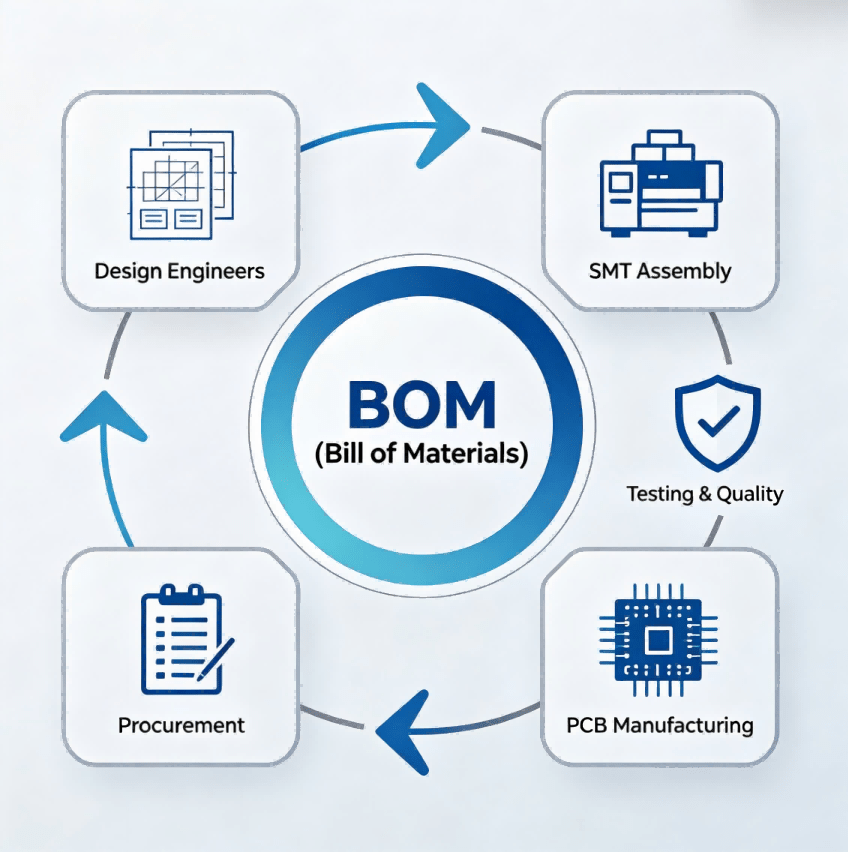
This guide is maintained by the HCJMPCBA engineering team and updated with production checklists. In practical terms, a PCB robot is the printed circuit board assembly that manages sensing, power conversion, communication, and actuation inside robotic equipment. A robot may contain one board or many interconnected boards depending on complexity. For OEM teams, success depends not only on design—but also on whether the electronics can be manufactured consistently at volume.
HCJMPCBA supports robotics customers with prototype builds, pilot runs, and mass production through controlled process logic: Method Number + Revision management, defined sample plans, validated test conditions, Raw Data reporting, and full traceability down to lot / batch / serial level.
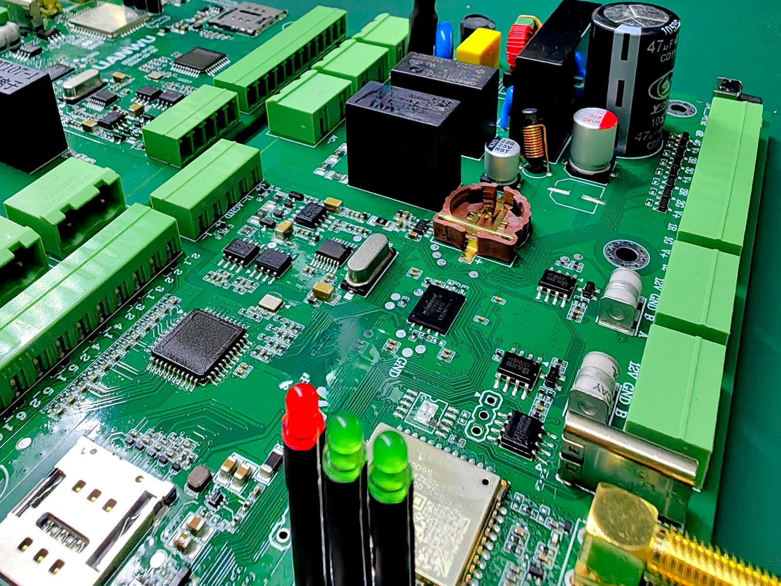
A PCB robot is the electronic control platform used inside a robot. It may include motor drivers, MCU or MPU control, wireless communication, sensors, safety circuits, battery management, and human-machine interfaces. In manufacturing terms, it is a robot circuit board or multiple circuit board assemblies integrated to make robotic functions reliable, repeatable, and scalable.
Robotic products often face harsher conditions than ordinary consumer devices:
Because of this, robotics PCBA usually needs stronger design margins, tighter assembly controls, and more test evidence than low-risk consumer electronics.
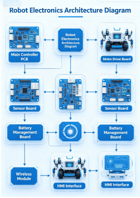
Pcb Robot Electronics Architecture Diagram Hcjmpcba
| Board Type | Main Function | Typical Components | Used In |
|---|---|---|---|
| Main Control Board | Decision logic and coordination | MCU, MPU, DDR, Flash | AMR, humanoid robot design, service robots |
| Motor Driver Board | Motion control | MOSFET, Gate Driver, Encoder IC | Robot arm, AGV, robotic assembly |
| Sensor Board | Environment perception | IMU, ToF, Pressure, Camera Interface | Inspection robot, humanoid parts |
| Power Board | Voltage conversion and charging | DC/DC, Charger IC, Fuse | Battery robots, mobile systems |
| Communication Board | Connectivity | Wi-Fi, BLE, CAN, Ethernet | IoT robot platforms |
Before layout begins, engineering teams should define:
A warehouse robot and a surgical assistant robot may both be “robots,” but their electronics requirements are radically different.
A professional robot diagram should separate high-noise and sensitive circuits:
This stage determines long-term stability more than cosmetic enclosure design.
Many robotics delays happen because prototypes ignore manufacturability. Good PCB robotics design should review:
At HCJMPCBA, DFM feedback is provided before production release to reduce respins and schedule loss.
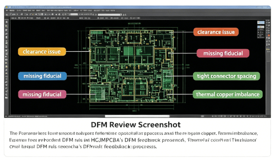
Hcjmpcba Pcb Robot Dfm Review Screenshot
A robot may stay in market for years. Therefore component selection should consider:
Low-cost parts with unstable availability can destroy production continuity.
Engineering samples should verify:
A prototype is not only for proving concept. It should generate measurable engineering evidence.
Mass production readiness includes:
This is where many startups struggle. Product design may be ready, but manufacturing systems are not.
| Control Element | What It Means | Customer Benefit |
|---|---|---|
| Method Number + Revision | Locked process parameters and approved build version | Repeatable output across batches |
| Sample Plan | Defined inspection quantity and acceptance logic | Reduced escape risk |
| Test Conditions | Controlled voltage, load, firmware, environment | Comparable test results |
| Raw Data | Machine logs and measurable outputs | Objective quality evidence |
| Traceability | Lot / batch / serial linkage | Fast root cause analysis |
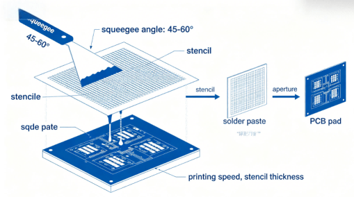
Robotics boards often use dense layouts, QFN, BGA, and fine-pitch devices. Stable placement and reflow profiles are essential.
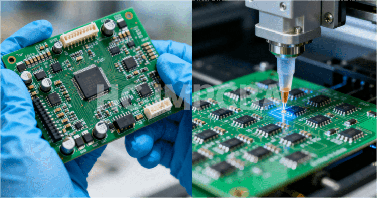
AOI Inspection
Automated optical inspection detects polarity errors, tombstones, insufficient solder, and missing parts before boards move downstream.
X-Ray for Hidden Joints
BGA and bottom terminated components may require X-ray confirmation.
Functional Test
Boards should be tested in real operating states: motors enabled, sensors connected, communications active.
Conformal Coating (When Required)
For moisture, dust, or industrial environments, coating may significantly extend service life.
Robotics hardware demands more than just placement; it requires extreme durability under dynamic stress. At HCJMPCBA, we address three critical robotics pain points during mass production:
High-Current Thermal Management: For motor driver boards, we utilize specialized Revision-controlled thermal profiles to ensure high-TG materials are soldered without latent stress.
Vibration Resistance: Robotic joints involve constant movement. We implement stringent Raw Data monitoring on solder paste volume (3D SPI) to ensure every solder joint meets IPC-Class 3 standards for mechanical strength.
System Consistency: Through our Method Number logic, we lock in every manufacturing parameter. Whether you are building 100 or 10,000 robotic units, the performance of the PCBA remains identical, batch after batch.
| Evidence | Why It Matters | Available for Robotics Projects |
|---|---|---|
| SPI / AOI Reports | Assembly quality visibility | Yes |
| X-Ray Images | Hidden solder joint validation | Yes |
| Functional Test Logs | Electrical performance evidence | Yes |
| Traceability Report | Failure containment speed | Yes |
A customer may successfully build ten prototype controllers but fail at 5,000 units because of inconsistent soldering, substituted components, and weak testing logic. By introducing controlled BOM approval, fixture-based testing, AOI gates, and serial traceability, production yield becomes stable and field returns drop significantly.
That is the difference between making electronics and building a scalable manufacturing system.
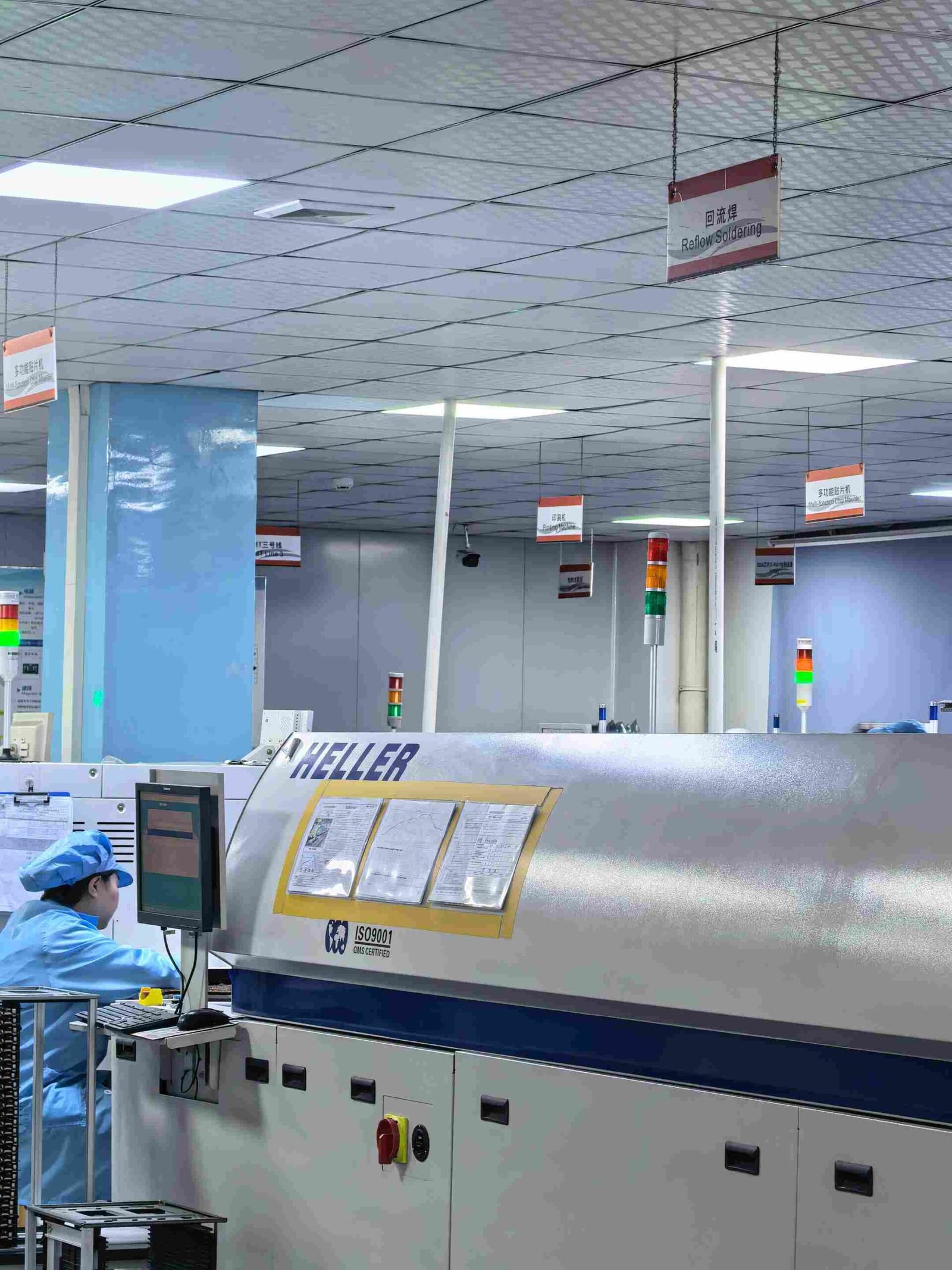
Hcjmpcba Smt Line
Q:What is a robot circuit board?
A:It is the PCB assembly controlling robot power, sensing, communication, and motion functions.
Q:How many PCBs does one robot need?
A:Simple products may use one board. Complex systems can use multiple boards connected by harnesses or backplanes.
Q:What is the difference between consumer PCBA and robotics PCBA?
A:Robotics usually needs stronger reliability, better thermal control, vibration tolerance, and longer lifecycle support.
Q:Can you build humanoid robot design electronics?
A:Yes. Multi-board systems with sensors, motion control, communication, and battery management can be supported depending on project requirements.
Q:Do robotics boards need conformal coating?
A:Not always. It depends on dust, humidity, condensation, and chemical exposure.
Q:Can HCJMPCBA support pilot run and mass production?
A:Yes. Many OEM customers begin with prototypes, then transition to low-volume and high-volume manufacturing.
Q:Why is traceability important?
A:It reduces downtime during failures by identifying affected materials or batches quickly.
All robot PCB assemblies shall be manufactured to the approved Method Number + Revision. No material or firmware change is permitted without documented approval. Production lots shall include test records, inspection evidence, and full traceability linking components, process data, and final serial numbers.
The future of robotics depends on dependable electronics. A strong PCB robot platform is not just a board—it is the foundation of safe movement, accurate sensing, and scalable commercialization. Whether the application is industrial automation, service robotics, humanoid parts development, or custom robot platforms, manufacturing discipline determines whether innovation reaches the market successfully.
For more information about PCBA services, please contact Guangzhou Huachuang Precision Technology(HCJMPCBA).
Update triggers: standard revision changes / recurring questions / production checklist updates.
Need to understand a 5 pin switch keyboard socket and how 3-pin vs 5-pin switches affect your keyboa
The article explores the significance of communication PCBA, its design challenges, trends, and high
Explore the fundamentals of circuit board design, from schematic creation to layout and manufacturin