High-Reliability PCB Warpage Prevention: Ensuring Performance in Medical, AI & Industrial Electronics
PCB warpage is a critical issue in medical devices, AI hardware, and industrial automation, where di

Formulated by Isaac Asimov in 1942, the Three Laws of Robotics are ethical rules designed to govern autonomous machine behavior. In modern hardware engineering, these principles translate into functional safety architectures, fail-safe PCB control circuits, and ISO/IEC-compliant hardware designs. This guide is maintained by the HCJMPCBA engineering team and updated with production checklists.
Takeaway 1: Ethical robotic laws demand physical and electrical hardware redundancy — fail-safe mechanisms, dual-channel watchdog circuits, and independent power domains ensure that when faults happen, the system detects them and drives to a defined safe state.
Takeaway 2: High-reliability PCBA manufacturing under IPC standards guarantees zero-failure execution in safety-critical robotics. IPC-A-610 Class 3 is the highest workmanship standard — it mandates 100% inspection (no sampling), full traceability, and the tightest acceptance criteria.
Takeaway 3: Complete traceability and rigorous testing transform abstract safety rules into verifiable manufacturing data — from lot/batch/serial tracking to raw electrical test logs that survive post-incident audits.
| Evaluation Metric | Standard Commercial PCBA | Safety-Critical Robotics PCBA (HCJMPCBA) |
|---|---|---|
| Design Review (DFM/DFT) | Basic design rule check | Full DFM + DFT review; Method Number + Revision controlled engineering change management |
| Testing Protocols | Sampling-based inspection | 100% AOI + 3D X-Ray + ICT + FCT with raw data logging |
| Traceability | Batch-level tracking | Full lot/batch/serial-level traceability down to each component |
| Component Sourcing | Standard distributor channels | Authorized distributors only; counterfeit mitigation; obsolescence management |
| Standard Compliance | IPC Class 2 or unspecified | IPC-A-610 Class 3 + IEC 61508 (SIL) + ISO 13849 (PL) alignment |
| Documentation | Basic COC | Full traceability docs, AOI/X-Ray reports, raw test logs, lot sheets |
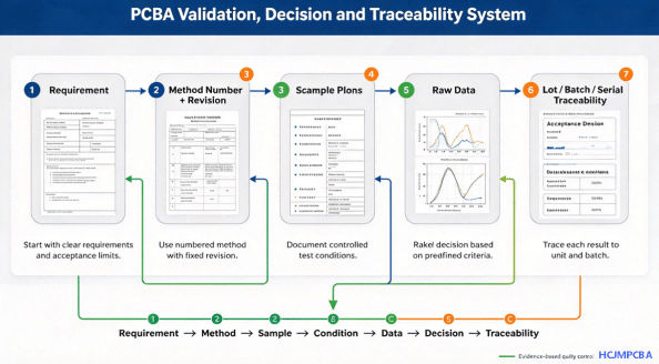
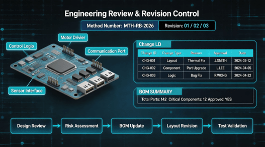
Every robotics PCBA project begins with a comprehensive engineering design review. Our team evaluates the design against DFM (Design for Manufacturing) and DFT (Design for Testability) principles. Each project is assigned a Method Number with strict Revision control — every change, from component substitution to layout optimization, is documented and version-controlled. This ensures firmware-hardware co-design integrity and provides a clear audit trail for safety certification.
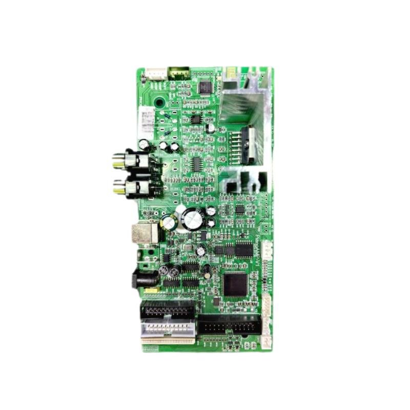
Robotics Controller Pcba
For safety-critical robotics applications, component integrity is non-negotiable. We source all active semiconductors and passive components exclusively from authorized distributors to eliminate counterfeit IC risks. A defined sample plan is established for each production run — first-article inspection validates component authenticity, date codes, and compliance with the approved BOM. Lot-level traceability begins at this stage, linking every component to its source certificate.
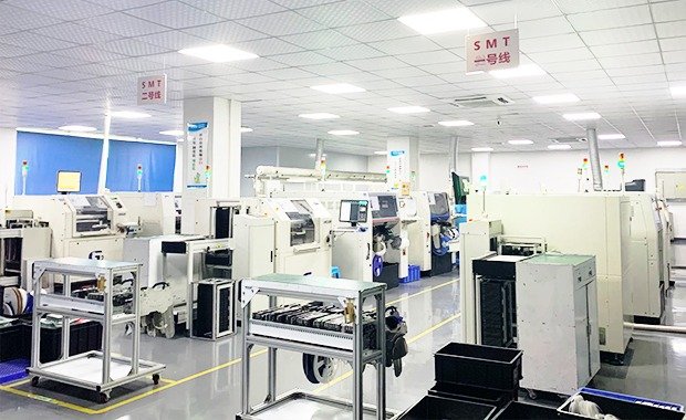
Robotics PCBA demands extreme placement accuracy — microcontrollers, BGAs, and QFNs require precise solder paste volume control (±15% volume gate via 3D SPI). Our SMT lines use closed-loop process control with Statistical Process Control (SPC) applied to paste volume, reflow peak temperature, and conveyor speed. For safety-critical joints, robotic soldering ensures repeatable solder volume, dwell time, and temperature control — eliminating the variability of manual processes.
Every board undergoes 100% 3D AOI inspection to verify component placement, solder joint quality, and alignment against IPC-A-610 Class 3 criteria. For BGA and QFN packages, 3D X-Ray inspection is mandatory — void ratio must be below 25% per joint for Class 3 compliance. This dual-inspection approach catches both surface-level defects and hidden subsurface issues that could compromise safety functions.
Ict (in Circuit Test)
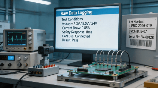
ICT (In-Circuit Test) verifies component-level soldering quality through bed-of-nails contact with test points. FCT (Functional Test) validates the complete system logic — safety response times, voltage rails, communication buses, and motor driver outputs. All test conditions are documented as Raw Data — not just pass/fail flags, but actual measured values (voltages, currents, response times) with timestamps. Each board receives a traceability lot/batch barcode linking it to every test result.
| Test Parameter | Standard / Specification | Acceptance Criteria | Provided Evidence |
|---|---|---|---|
| SMT Solder Joint Integrity | IPC-A-610 Class 3 | 100% inspection; no defects; complete wetting | 3D AOI report + X-Ray void analysis |
| In-Circuit Testing (ICT) | IPC-9252 / Customer DFT | Test point coverage ≥ 90%; opens/shorts detected | ICT test log with failed nodes |
| Functional Safety Response | IEC 61508 (SIL) / ISO 13849 (PL) | Safe state achieved within required response time | FCT raw data log with timing measurements |
| Thermal Stress / Aging | IPC-9701 / JESD22-A104 | -40°C to +125°C cycling; 50–100 cycles | Thermal cycle test report with solder joint integrity verification |
| Component Traceability | IPC-1752 / Customer spec | Full lot/batch/serial traceability | Lot traceability sheets + authorized distributor certificates |
| Conformal Coating | IPC-CC-830B | Silicone/acrylic for moisture/chemical resistance | Coating thickness and coverage inspection report |
Mistake 1: Overlooking component obsolescence and counterfeit IC risks in safety controllers. Counterfeit or end-of-life components can invalidate an entire SIL or PL certification. Always require authorized distributor sourcing with full traceability.
Mistake 2: Neglecting rigorous thermal management on high-current motor driver PCBs. Heat is often underestimated. Insufficient copper weight, missing thermal vias, or poor MOSFET heat spreading leads to resets, reduced battery life, and premature failure.
Mistake 3: Failing to enforce strict revision tracking (Method Number + Revision) for firmware-hardware co-design. A firmware update that doesn’t align with the hardware revision can create unpredictable safety behavior. Every change must be documented and approved.
Mistake 4: Relying on basic sample testing instead of 100% functional testing for safety logic circuits. For safety-critical functions, sampling is not acceptable — Class 3 mandates 100% inspection. A single undetected fault can have catastrophic consequences.
Mistake 5: Ignoring component batch-level traceability for active semiconductors. Without lot-level traceability, a field failure cannot be traced back to its root cause, making recalls impossible and certification audits unpassable.
Industrial robotic arms, autonomous mobile robots (AMRs), collaborative robots (cobots), medical surgical assistants, and automated guided vehicles (AGVs) all depend on hardware-level safety to prevent catastrophic operational failures. In these applications, a single solder joint failure on a safety controller PCBA can mean the difference between a controlled stop and an uncontrolled collision. Cobots work hand-in-hand with humans in factories and must therefore meet the highest functional safety requirements — typically targeting ISO 13849 PL d (Category 3 architecture with redundant channels and monitoring) or IEC 61508 SIL 2–3. Certification to these standards depends on redundancy, diagnostic coverage, independence against common-cause failures, isolation integrity, and audit-ready evidence.
Q1: What is 3 laws of robotics, and how do they influence hardware design?
Asimov’s Three Laws — (1) do not harm humans, (2) obey human orders, (3) protect own existence — translate in engineering into functional safety architectures. Hardware must incorporate fail-safe circuits, redundant safety channels, and diagnostic coverage to ensure the system can detect faults and drive to a safe state.
Q2: Why is component traceability essential for robotic safety control boards?
Traceability links every component to its source, enabling root-cause analysis during field failures and satisfying certification audit requirements. Without lot/batch/serial tracking, a single failure can’t be investigated or contained.
Q3: What test conditions are required for high-reliability robotics PCBA?
Mandatory tests include 100% AOI, 3D X-Ray (BGA void <25%), ICT for solder joint verification, FCT for system logic validation, and thermal cycling (-40°C to +125°C). All tests must produce raw data logs, not just pass/fail indicators.
Q4: How does HCJMPCBA ensure revision control during mass production?
Every project is assigned a Method Number with strict Revision tracking. Any change — component substitution, layout modification, or process adjustment — is documented and requires customer approval before implementation.
Q5: What manufacturing standards govern robotic electronic assemblies?
Robotics PCBA typically requires IPC-A-610 Class 3 (highest reliability), with functional safety alignment to IEC 61508 (SIL), ISO 13849 (PL), and IEC 62061.
Q6: How to request a custom sample plan for a new robotics controller board?
Contact HCJMPCBA with your PCB design files, BOM, and functional safety requirements. Our engineering team will review and propose a defined sample plan covering first-article inspection, testing protocols, and qualification criteria.
| Document | What It Contains | When You Receive It |
|---|---|---|
| AOI/X-Ray Defect Reports | 100% inspection results with defect images and classification | Per batch, prior to shipment |
| Raw Electrical Test Logs | ICT and FCT measured values (voltages, currents, response times) with timestamps | Per batch, prior to shipment |
| Authorized Distributor Certificates | Proof of component authenticity for all active semiconductors | Per BOM revision |
| Lot Traceability Sheets | Lot/batch/serial linkage from component receipt to final assembly | Per batch, with shipment |
| Thermal Cycling Test Reports | -40°C to +125°C cycle results with solder joint integrity verification | Per qualification run |
| PFMEA & Control Plan | Process failure mode analysis linking SMT defects to safety function degradation | Upon request |
From prototype builds to pilot runs and mass production, HCJMPCBA delivers robotics PCBA with controlled process logic: Method Number + Revision management, defined sample plans, validated test conditions, Raw Data reporting, and full traceability down to lot/batch/serial level. Our engineering team brings decades of experience in high-reliability electronics for industrial automation, robotics, and safety-critical applications.
For more information about PCBA services, please contact Guangzhou Huachuang Precision Technology (HCJMPCBA).
Update triggers: standard revision changes / recurring questions / production checklist updates.
PCB warpage is a critical issue in medical devices, AI hardware, and industrial automation, where di
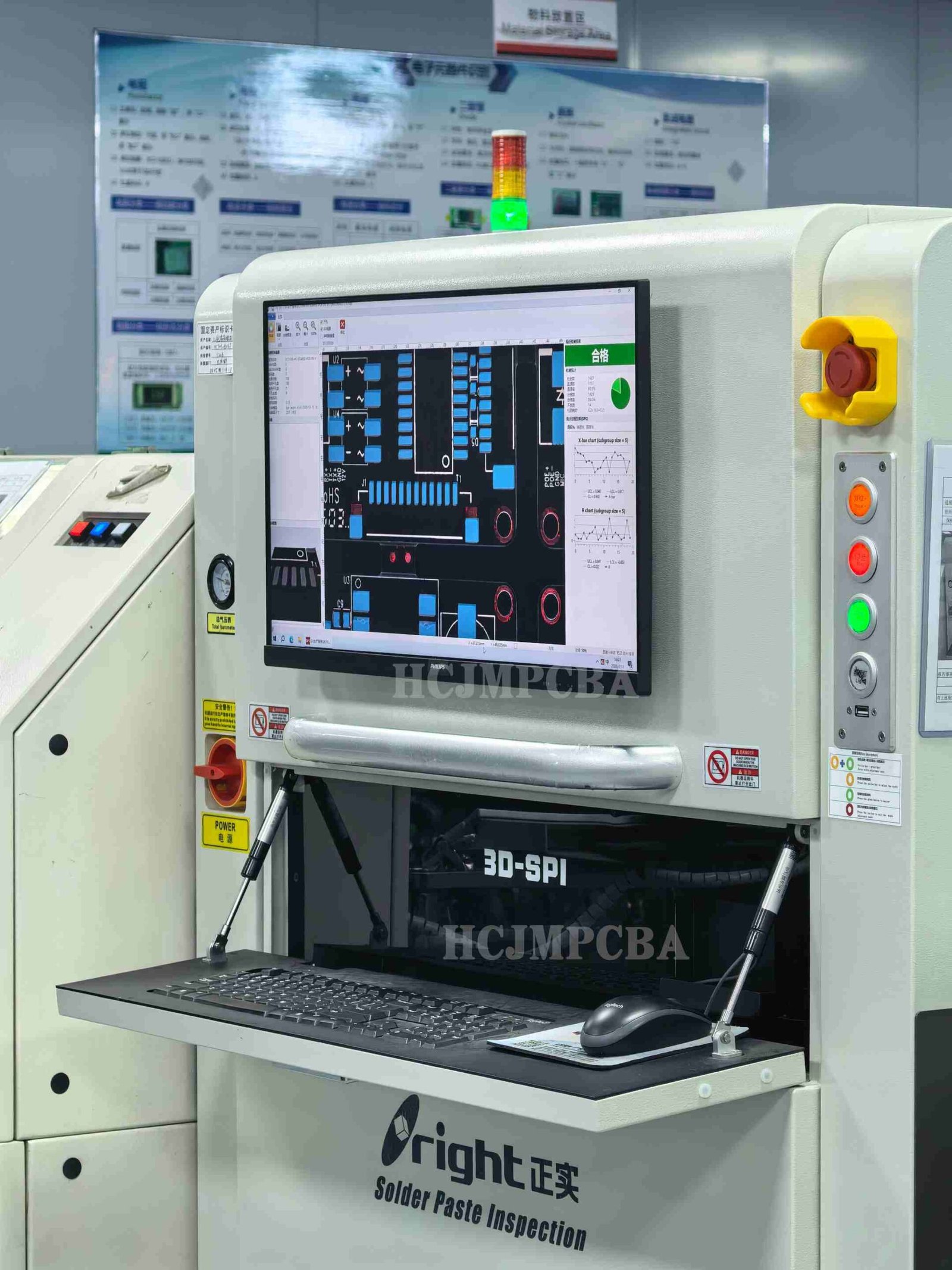
In high-mix PCBA environments, paste volume variability at changeover is the root cause of over 60%
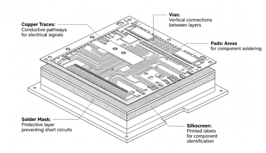
PCB failures — physical damage, component failure, trace damage, and power issues — disrupt prod