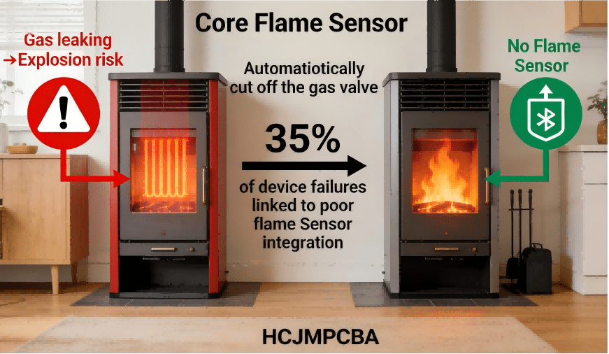
For PCB/PCBA OEM engineers, procurement decision-maker,and cross-industry buyers, integrating safety-critical components like flame sensors is non-negotiable. A faulty or poorly integrated flame sensor doesn’t just lead to product recalls—it poses life-threatening risks: unburned gas buildup, equipment explosions, and costly downtime. Industry data shows that 35% of field failures in gas-powered devices stem from improper flame sensor function or PCBA integration errors .
But what does a flame sensor do, exactly? And how does it work to protect equipment and users? This comprehensive guide answers these questions and more, while revealing PCB/PCBA integration best practices that only decades of engineering expertise can deliver. Whether you’re designing a residential furnace, industrial boiler, or gas heater, understanding flame sensor technology and its seamless integration into PCBA systems is the key to building safe, compliant, and reliable products.
At HCJMPCBA, we specialize in turning complex safety component requirements into robust PCB/PCBA solutions. Our IPC 6012-compliant processes and ISO-certified supply chain ensure that flame sensors perform flawlessly in even the harshest environments—from high-temperature industrial settings to precision consumer electronics.
A flame sensor (also called a flame detector sensor or flame detection sensor) is a safety-critical device designed to verify the presence of a flame during combustion processes . Its primary mission is to prevent unburned fuel (usually gas or oil) from accumulating—an oversight that can lead to explosions, carbon monoxide poisoning, or catastrophic equipment damage.
Flame Verification: Confirms that fuel ignites successfully (e.g., in a furnace or water heater) and remains lit during operation.
Emergency Shutdown: Triggers the gas valve furnace to close immediately if no flame is detected, cutting off fuel supply.
Fault Signaling: Alerts control systems to abnormal conditions (e.g., weak flame, sensor contamination) that could compromise safety.
Efficiency Optimization: Ensures consistent combustion by monitoring flame stability, reducing energy waste and emissions.
For example, in a residential furnace, the flame sensor acts as a “safety guard”: when the thermostat calls for heat, the furnace ignites the burner, and the flame sensor verifies the flame’s presence . If the flame goes out unexpectedly (due to a draft or fuel interruption), the sensor sends a signal to shut off the gas valve within milliseconds—preventing dangerous gas buildup in the home.
In industrial settings like power plants or chemical facilities, flame sensors play an even more critical role: they monitor large-scale combustion processes and integrate with emergency shutdown systems to protect personnel and equipment from fire or explosion risks .
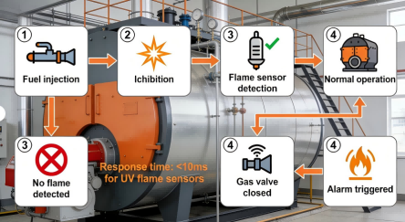
Flowchart Of Flame Sensor Functions
To understand how a flame sensor works, it’s critical to distinguish between its three primary types—each with unique operating principles tailored to specific applications. The technology hinges on detecting unique electromagnetic radiation or ionic activity produced by flames, then converting that signal into actionable electrical feedback for the PCBA control system.
An infrared flame sensor (or IR flame sensor) detects the infrared radiation (wavelength 0.76–1000μm) emitted by burning fuels . Flames from hydrocarbon fuels (e.g., coal, oil, natural gas) produce intense infrared radiation from hot carbon particles and water vapor—this is what the sensor’s photocell captures.
- The sensor’s infrared detector (a photodiode or thermopile) converts IR radiation into a weak electrical current.
- A signal amplification circuit on the PCBA boosts this current to a usable level.
- The PCBA control system analyzes the signal’s intensity and frequency: if it matches the signature of a valid flame, the system keeps the fuel valve open; if not, it shuts down fuel flow.
- Resistant to ambient light and dust interference (ideal for industrial environments).
- Long lifespan (5–10 years) and high temperature tolerance (up to 150°C) .
- Suitable for large-scale combustion systems like boilers and incinerators.
A ultraviolet flame sensor targets the UV radiation (wavelength 10–400nm) produced by flame-specific chemical reactions . Unlike sunlight (which has UV wavelengths >300nm, blocked by the atmosphere), flames emit short-wave UV radiation that the sensor’s UV-sensitive tube detects.
The sensor’s UV tube contains a gas that ionizes when exposed to flame UV radiation.
Ionization allows a small current to flow through the tube, signaling the presence of a flame.
Most UV sensors include a 2–3 second time delay to avoid false alarms from lightning or welding arcs .
Ultra-fast response time (<10ms) for critical safety applications (e.g., gas turbines, Torch System).
High selectivity—ignores non-flame light sources, reducing false alarms .
Ideal for clean-burning fuels like natural gas and propane.
Common in residential furnaces and water heaters, ionization sensors (also called flame rectification sensors) rely on flame rectification—a process where flames conduct and “rectify” electrical current .
The sensor’s metal rod (flame rod) extends into the furnace flame.
The PCBA sends a small AC current through the rod; the flame’s ions convert this AC current to DC.
The control system detects the DC current as proof of a valid flame. If no current is detected (no flame), the gas valve closes.
Low cost and simple design, perfect for consumer appliances.
Direct integration with standard furnace PCBA systems.
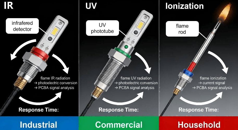
Comparison Diagram Of The Working Principles Of Three Flame Sensors
Not all flame sensors are created equal—choosing the right type depends on your application, fuel type, and environmental conditions. Below is a detailed comparison of the most common types, along with their specific PCB/PCBA integration needs (critical for OEM engineers and procurement teams).
Signal Integrity: Flame sensor signals are often weak—PCB layouts must minimize noise with proper grounding (star ground) and short trace lengths .
Environmental Hardening: For industrial use, PCBA must resist moisture, dust, and extreme temperatures (use conformal coating and metal-core PCBs).
Compliance: Meet IEC 61508 (functional safety) and IPC 6012 (PCB quality) standards for global market access .
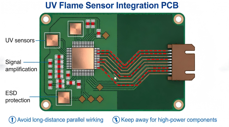
Pcbpcba Flame Sensor Integration Layout Diagram
Flame sensors are ubiquitous across industries, but their specific roles and PCBA integration needs vary by device. Below are the most common applications, with a focus on how flame sensors function and what OEMs need to know for successful PCB/PCBA design.
A furnace flame sensor (or furnace flame rod) is the unsung hero of home heating. Here’s how it works:
- When the thermostat calls for heat, the furnace’s igniter lights the gas burner.
- The flame sensor’s metal rod extends into the flame, conducting current via flame rectification .
- If the sensor detects current (proof of flame), the gas valve remains open; if not, it shuts off gas within 2–3 seconds.
- Dirty Sensor Rod: Dust or corrosion blocks current flow—HCJMPCBA integrates self-cleaning circuit logic into PCBA to reduce maintenance.
- Wiring Interference: Signal noise triggers false shutdowns—our PCB layouts use shielded wiring and noise filters.
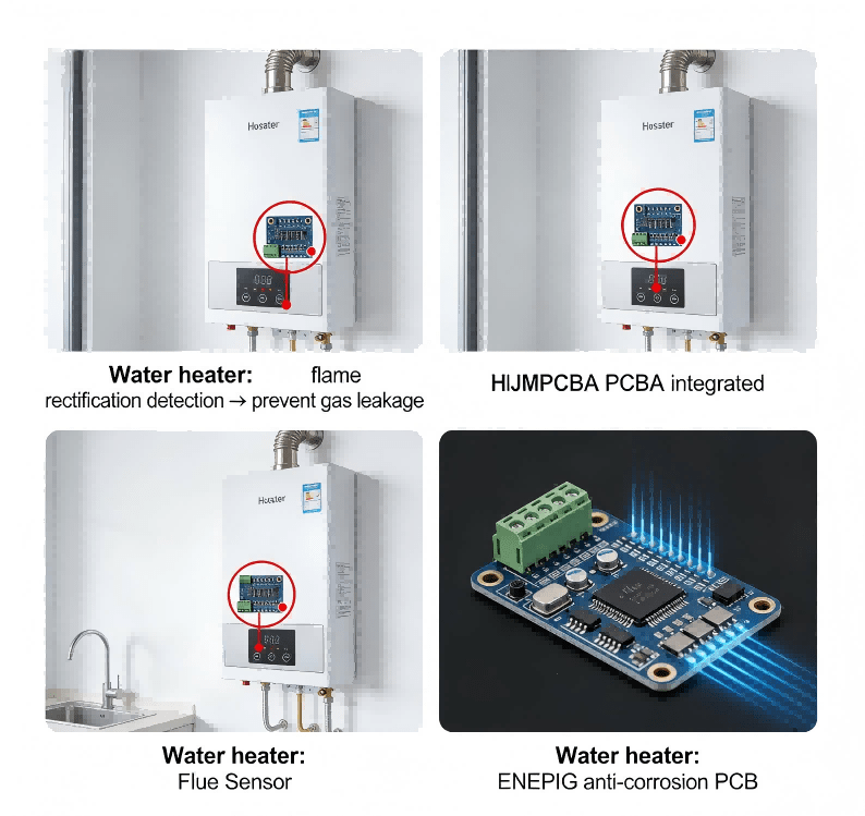
In gas water heaters, the flame sensor prevents unburned gas from accumulating in the tank. Key functions include:
- Verifying the pilot light or burner flame is lit.
- Shutting off the gas valve if the flame extinguishes (e.g., from a strong draft).
Water heater PCBA must handle high humidity—HCJMPCBA uses ENEPIG surface treatment to resist corrosion and moisture damage .
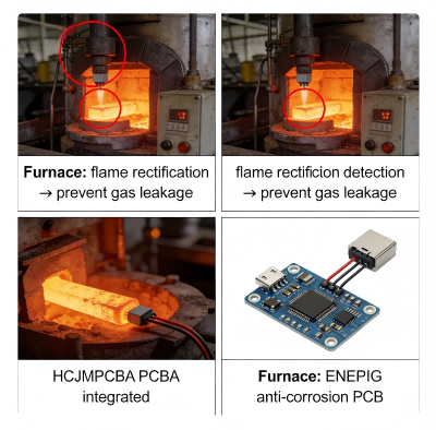
Industrial boilers (used in power plants, manufacturing) require rugged flame sensors that operate in high-temperature, dusty environments. The sensor’s role:
- Monitor large-scale flame stability for efficient combustion.
- Trigger emergency shutdowns if flame is lost to prevent boiler explosions.
We integrate IR flame sensors with thermal vias and heat sinks on PCBA, ensuring reliable performance at temperatures up to 180°C.
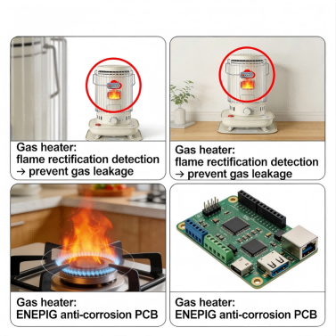
Portable and wall-mounted gas heaters rely on compact flame sensors to ensure safety in homes and offices. Key features:
Fast response time (<50ms) to shut off gas if flame is lost.
Low power consumption for battery-operated models.
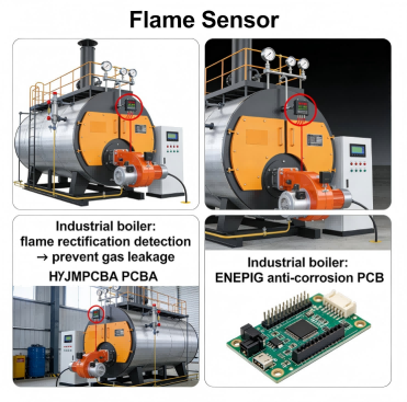
Functional Display Diagram Of Flame Sensors In Four Major Application Scenarios 1
Functional Display Diagram Of Flame Sensors In Four Major Application Scenarios 4
Functional Display Diagram Of Flame Sensors In Four Major Application Scenarios 3
Functional Display Diagram Of Flame Sensors In Four Major Application Scenarios 2
For PCB/PCBA engineers and maintenance teams, knowing how to test and troubleshoot a flame sensor is critical to reducing downtime and warranty claims. Below is a step-by-step guide to testing, plus solutions for the most common problems.
Step 1: Safety Precautions First
Disconnect power and gas supply to the device before testing.
Wear protective gear (gloves, goggles) to avoid burns or electrical shock.
Step 2: Visual Inspection
Check the sensor rod (ionization type) for corrosion, dust, or damage—clean with a soft brush if dirty.
Inspect PCB wiring for loose connections, fraying, or short circuits .
Verify the sensor is positioned correctly (aligned with the flame path).
Step 3: Multimeter Testing (Ionization & IR/UV Sensors)
For Ionization (Furnace) Sensors:
Set the multimeter to measure microamps (μA).
Disconnect the sensor wire from the PCBA control board.
Connect the multimeter probes in series between the sensor and the wire.
Reconnect power and ignite the furnace—normal readings range from 1–10 μA .
If no reading: Replace the sensor or check for PCB wiring issues.
For IR/UV Sensors:
Set the multimeter to measure voltage (DC 0–5V).
Connect probes to the sensor’s signal output pins on the PCBA.
Expose the sensor to a flame (e.g., lighter) from 10–15cm away.
A valid signal will show a voltage drop (0.5–2V) on the multimeter .
No voltage change: Test the sensor’s power supply on the PCBA (typically 12V or 24V DC).
Step 4: Common Flame Sensor Issues & Solutions
| Issue |
Cause |
HCJMPCBA PCB/PCBA Fix |
| False Shutdowns |
Signal interference or dirty sensor |
Integrate noise filters and self-cleaning logic into PCBA |
| No Flame Detection |
Misalignment or faulty wiring |
Design PCB with sensor positioning guides and continuity checks |
| Short Sensor Lifespan |
High temperature or moisture |
Use metal-core PCBs and conformal coating for environmental protection |
| Error Codes (e.g., Traeger 0024/0031) |
Loose connections or firmware bugs |
Implement PCB connector locks and over-the-air (OTA) firmware updates |

Schematic Diagram Of Flame Sensor Testing Process
Integrating a flame sensor into a PCB/PCBA is more than soldering components—it requires a holistic approach to safety, reliability, and compliance. Below is HCJMPCBA’s proven framework, developed over 15+ years of serving global OEMs.
1. Pre-Design Consultation & Requirements Mapping
Collaborate with your team to define key parameters: sensor type (IR/UV/ion), operating temperature, response time, and compliance standards (IEC 61508, IPC 6012).
Conduct a failure modes and effects analysis (FMEA) to identify potential integration risks (e.g., signal noise, thermal stress) .
2. PCB Design for Flame Sensor Compatibility
Component Placement: Position the flame sensor connector near the edge of the PCB for easy access; keep signal amplification circuits close to the sensor to minimize noise.
Trace Routing: Use short, wide traces for sensor signals (minimize resistance); implement ground planes to reduce electromagnetic interference (EMI) .
Thermal Management: Add thermal vias and heat sinks for high-temperature applications (critical for IR sensors in industrial boilers).
3. Component Sourcing & Quality Control
Source genuine flame sensors from ISO-certified suppliers (HCJMPCBA’s supply chain includes Honeywell, Siemens, and custom-manufactured sensors).
Test all components for sensitivity, response time, and durability before integration.
4. DFM (Design for Manufacturability) Validation
Use automated DFM tools to check for soldering issues, trace width compliance, and component compatibility.
Conduct manual reviews by HCJMPCBA’s senior engineers to catch edge cases (e.g., EMI from nearby power components).
5. Prototype Testing & Iteration
Build functional prototypes to test flame sensor performance in real-world conditions (temperature cycling, humidity, vibration).
Validate PCB/PCBA with flame simulation tools to ensure response time meets safety requirements.
6. Mass Production & Quality Assurance
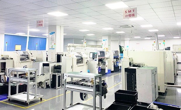
Manufacture PCBA in ISO 9001-certified facilities using pick-and-place machines for precision.
Conduct 100% functional testing (flame detection accuracy, signal integrity, emergency shutdown response) before shipment.
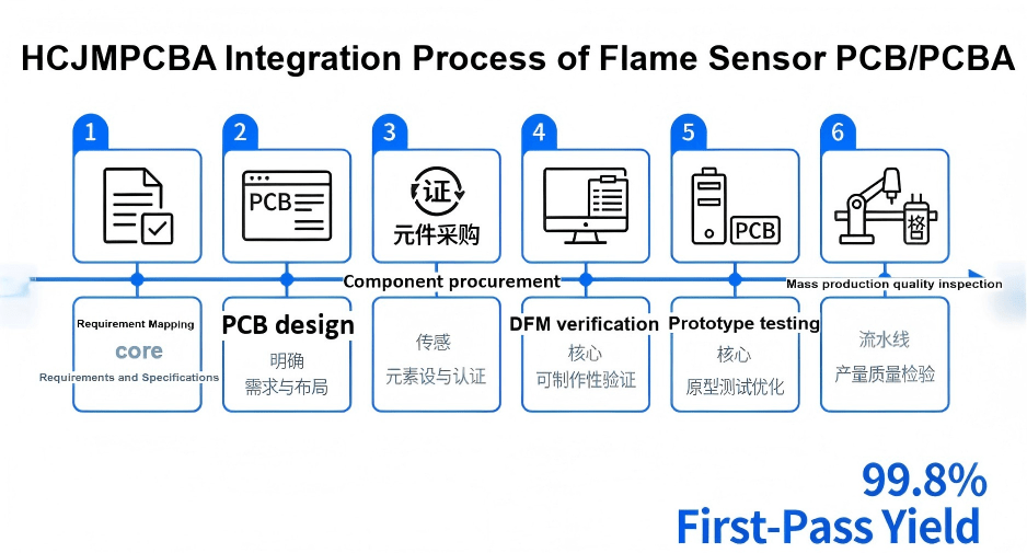
Hcjmpcba Flame Sensor Pcbpcba Integration Flowchart
What sets HCJMPCBA apart from other PCB/PCBA manufacturers? Our deep expertise in safety-critical components like flame sensors, combined with a customer-centric process that reduces risk and delivers value.
1. Safety-Centric Engineering
Our engineers are certified in IEC 61508 (functional safety) and IPC 6012 (PCB standards), ensuring flame sensor integration meets global safety requirements.
We implement redundant circuits in mission-critical applications (e.g., industrial boilers) to eliminate single points of failure.
2. Customization for Every Application
Whether you need a compact PCB for a portable gas heater or a rugged PCBA for a nuclear facility, we tailor designs to your specific needs.
Our in-house lab can simulate extreme environments (temperature, humidity, vibration) to validate performance.
3. Supply Chain Reliability
We source 100% genuine flame sensors and components from trusted suppliers, with no counterfeits—critical for safety devices.
Our inventory includes hard-to-find sensors (e.g., UV flame sensors for aerospace) and offers 48-hour lead times for urgent orders.
4. Quality Assurance & Compliance
ISO 9001 and IPC 6012 Class 3 certification ensures PCBA meet the highest quality standards.
Every batch undergoes flame detection accuracy testing, signal integrity analysis, and environmental stress screening.
5. End-to-End Support
From pre-design consultation to post-delivery technical support, our team is available to address questions and resolve issues.
We provide detailed documentation (schematic diagrams, test reports) to simplify your certification process.

Hcjmpcba Capability Display Infographic
A global manufacturer of industrial furnaces approached HCJMPCBA with a critical challenge: their existing flame sensor PCBA had a 12% failure rate, leading to costly recalls and lost customer trust. The issues included false shutdowns, short sensor lifespans, and non-compliance with EU safety standards.
Conducted FMEA to identify root causes: signal noise from poor PCB layout, low-quality components, and inadequate thermal management.
Redesigned the PCB with:
- Shielded wiring and noise filters to eliminate false signals.
- Metal-core PCB and thermal vias to handle high temperatures.
- ENEPIG surface treatment for corrosion resistance .
Sourced genuine IR flame sensors from Honeywell with a 10-year lifespan.
Implemented IEC 61508-compliant redundant circuits for fail-safe operation.
Failure rate dropped to 0.2% (well below industry average).
The OEM achieved EU safety certification and expanded into new markets.
Cost savings of 35% from reduced recalls and maintenance.
A flame supervision device (FSD) is a system that includes a flame sensor, control board, and gas valve. It monitors flame presence and shuts off fuel if the flame is lost—common in furnaces, boilers, and commercial kitchens.
Furnace flame sensors (ionization type) use flame rectification for cost-effectiveness, while industrial sensors (IR/UV) prioritize durability, long-range detection, and resistance to harsh environments.
For residential devices: Annually during maintenance. For industrial equipment: Monthly, or as part of a predictive maintenance program. HCJMPCBA’s PCBA includes self-testing logic to reduce manual checks.
Yes—common PCB-related issues include: weak power supply to the sensor, signal noise, loose connections, and faulty amplification circuits.
Key standards include IPC 6012 (PCB quality), IEC 61508 (functional safety), and regional standards (e.g., UL for North America, CE for Europe).
A flame sensor is more than a component—it’s a lifeline that prevents disasters in homes, factories, and critical infrastructure. For PCB/PCBA OEM engineers and procurement decision-maker,choosing the right integration partner is just as critical as selecting the sensor itself.
HCJMPCBA’s 15+ years of expertise in safety-critical PCB/PCBA design, IPC 6012 compliance, and flame sensor integration ensures your products are safe, reliable, and market-ready. Our end-to-end process—from pre-design consultation to mass production—reduces risk, cuts costs, and delivers peace of mind.
Whether you’re designing a residential furnace, industrial boiler, or gas heater, we have the engineering know-how and supply chain reliability to bring your product to life.