Guangzhou Huachuang Precision Technology Co., Ltd.: A Journey of Excellence in Electronics Manufacturing
Since its establishment in 2010,Guangzhou Huachuang Precision Technology Co.,Ltd.has focused on the
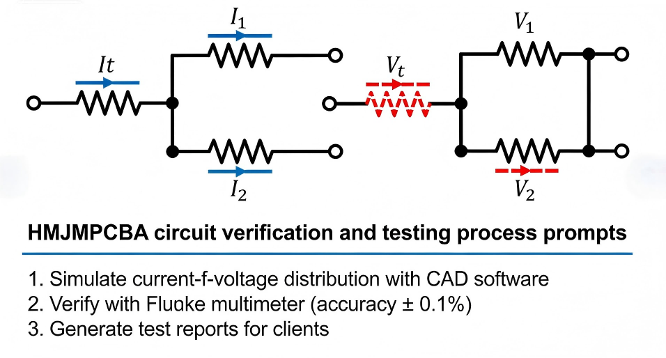
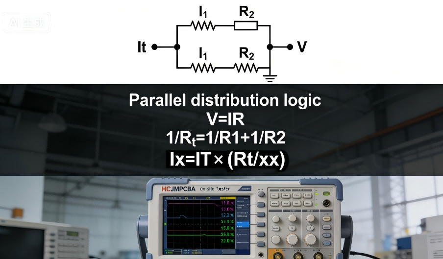
Accurate circuit analysis is foundational to PCBA reliability. Two of the most important analytical tools engineers use are the current divider rule and the voltage divider formula — essential for understanding how currents and voltages distribute through circuit networks. The current divider calculates how total current splits among parallel branches, while the voltage divider determines how supply voltage drops across components in series. Mastering these rules helps avoid common PCBA failures such as sensor misbias, power imbalance, or component overheating.
Both sensor circuits and power modules require precise evaluation of current distribution and voltage levels to prevent signal distortion, unexpected load conditions, and PCB failures during system integration. In this guide, we break down both formulas, compare their differences, and explain how HCJMPCBA helps validate and test division logic during PCBA design and assembly.
Pcba Current Voltage Distribution Scenarios Hcjmpcba
A current divider is a parallel circuit that splits the total input current among multiple branches connected across the same voltage. Because each branch sees the same voltage, the portion of total current flowing through each branch depends on the relative resistances of the branches. Basic Electronics Tutorials
In electronics, the current entering a parallel combination of resistors divides in such a way that lower resistance branches receive more current. This is due to the inverse relationship between resistance and current flow defined by Ohm’s Law.
For resistors R1,R2,…,RnR_1, R_2, …, R_n in parallel, the current through a specific branch RxR_x is given by:
Where:
IxI_x = current through branch xx
ItotalI_{total} = total current entering the parallel network
RtotalR_{total} = equivalent resistance of the parallel network
RxR_x = resistance of branch xx
This formula follows from the fact that in a parallel circuit all branches share the same voltage and current divides inversely with resistance. Basic Electronics Tutorials
Key point: The current divider rule applies only to parallel circuits, where the same voltage appears across each branch.
Typical use: Determine how much current flows through each branch of a power distribution network in a PCBA, such as bias networks or parallel sensor lines.
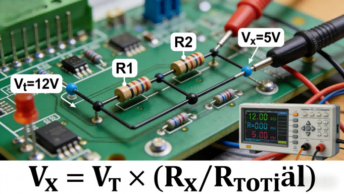
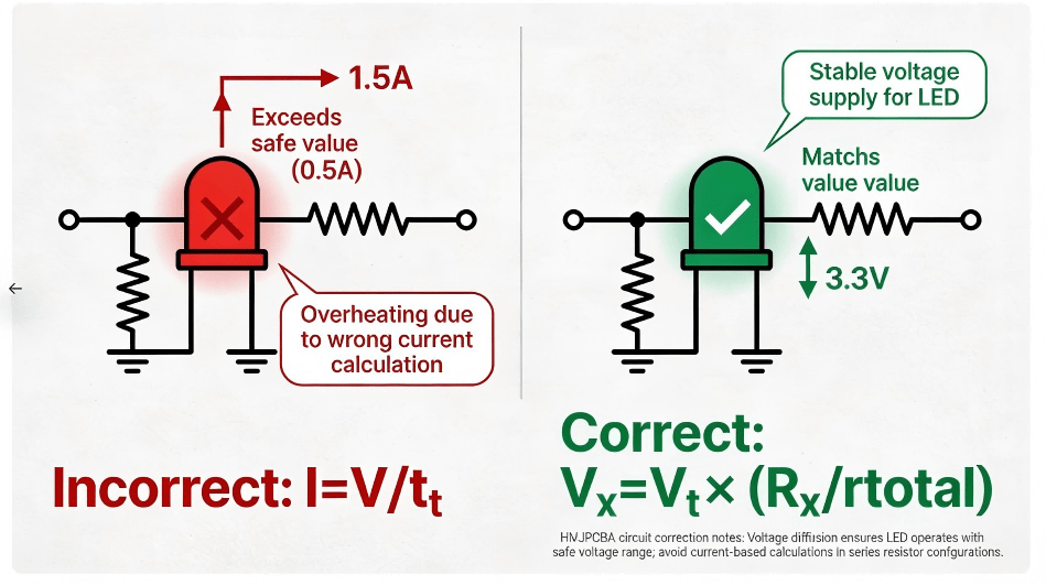
A voltage divider is a series circuit that splits the total supply voltage into proportional voltage drops across series components. Because the same current flows through each component in a series circuit, the voltage across each is proportional to its resistance.
Voltage dividers are fundamental for creating reference voltages or reducing voltage levels before feeding sensitive components (e.g., MCU inputs).
In a series network of resistors, the voltage drop VxV_x across a resistor RxR_x is:
Vx=Vtotal×RxRtotalV_x = V_{total} \times \frac{R_x}{R_{total}}
Where:
VxV_x = voltage across component xx
VtotalV_{total} = total supply voltage
Rtotal=R1+R2+…+RnR_{total} = R_1 + R_2 + … + R_n
This formula comes directly from applying Ohm’s Law and Kirchhoff’s Voltage Law (the sum of voltage drops in a loop equals the source voltage).
Typical use: Create precise reference voltages for analog-to-digital converters, biasing amplifiers, or feeding control logic in PCBA designs.
Voltage Distribution Application In Pcba Hcjmpcba
| Aspect | Current Divider | Voltage Divider |
|---|---|---|
| Circuit Type | Parallel | Series |
| Main Quantity Divided | Current | Voltage |
| Basic Condition | Equal voltage across branches | Equal current through components |
| Core Formula | Ix=Itotal×(Rtotal/Rx)I_x = I_{total} \times (R_{total}/R_x) | Vx=Vtotal×(Rx/Rtotal)V_x = V_{total} \times (R_x/R_{total}) |
| Use Case in PCBA | Distributes supply current | Reduces voltage for sensors/logic |
| Kirchhoff Law | KCL (current sum) | KVL (voltage sum) |
| Valid If | Branches in parallel | Components in series |
| Component Behavior | Lower resistance => more current | Larger resistance => larger voltage drop |
| Application Example | Parallel load balancing | Reference voltage creation |
| Common Misuse | Applied to series circuits | Applied with varying loads |
| These concise comparisons help engineers choose the correct analysis formula. |
To illustrate how current division works in practice, consider a simple parallel network:
Example: Two resistors R1=4ΩR_1 = 4Ω and R2=12ΩR_2 = 12Ω share a total current of 4A.
Equivalent resistance Rtotal=3ΩR_{total} = 3Ω.
Current through R1R_1:
I1=4A×3Ω4Ω=3AI_1 = 4A \times \frac{3Ω}{4Ω} = 3A
Current through R2R_2:
I2=4A×3Ω12Ω=1AI_2 = 4A \times \frac{3Ω}{12Ω} = 1A
Here the smaller resistance draws more current, consistent with the rule.
Accurate application of the current divider rule and voltage divider formula directly impacts PCBA performance, particularly in the following areas:
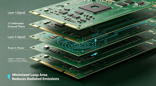
Power distribution networks – Avoid hot spots and ensure balanced currents.
Signal conditioning – Maintain stable reference voltages for ADC/Sensor interfaces.
Load sharing – Prevent overloading a single branch of your design.
Knowing how to verify these formulas through simulation and measurement helps reduce errors during PCB development and production.
Flowchart For Derivation Of Current Distribution Formula Hcjmpcba
HCJMPCBA supports PCBA designers and buyers with capabilities that ensure correct circuit division behavior in finished products:
Custom Simulation & Validation: Using CAD tools to simulate current and voltage dividers before hardware production.
Advanced Measurement Tools: Oscilloscopes and precision source meters verify divider behavior under real load conditions.
Standardized Test Reports: Delivered with PCBA batches — showing measured results align with theoretical divider calculations.
These processes reduce procurement risk, prevent field failures, and improve overall product reliability — especially for high-precision or safety-critical electronics.
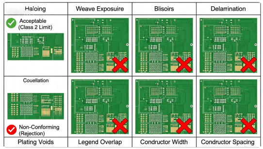
 Comparison Of Common Error Cases Hcjmpcba Current Divider
Q1: Can the current divider rule be used in AC circuits?
Yes. By replacing resistances with impedances (Z), current division still applies in AC networks.
Q2: What’s the difference between current divider law and current divider rule?
They refer to the same principle — describing how current splits among parallel branches.
Q3: Does voltage division work for more than two resistors?
Yes. The voltage divider formula extends to any number of series components.
Understanding the difference between the current divider rule and voltage divider formula — and knowing when to apply each — is essential for reliable PCBA design and analysis. Accurate current and voltage division calculations ensure balanced power distribution, stable reference levels, and robust PCB performance. ■
For engineers and procurement teams looking to validate these calculations in real hardware, HCJMPCBA’s customized simulation, testing, and verification services provide peace of mind and improved product quality.
🔹 Learn more about PCBA services, please contact Guangzhou Huachuang Precision Technology.
Since its establishment in 2010,Guangzhou Huachuang Precision Technology Co.,Ltd.has focused on the
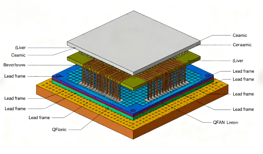
Discover what a QFN package with lid really means — its structure, advantages, thermal and electri

Learn 5 powerful customer communication strategies that position HCJMPCBA as one of the best PCB man