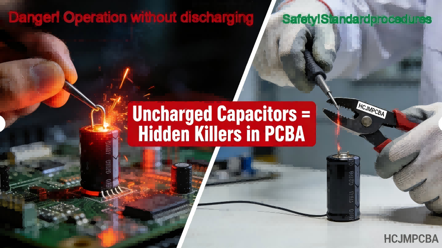
10 Compelling Reasons Why Discharging Capacitors Is Non-Negotiable + Expert’s Step-by-Step Guide on How to Discharge a Capacitor Safely
Discharging capacitors is a critical safety and quality control step in electronics and PCBA work. T
Solder used in electronics manufacturing is a metallic alloy designed to create permanent electrical and mechanical connections between components and printed circuit boards. Traditional lead solder consists primarily of tin and lead (SnPb), while modern lead free solder typically uses tin-silver-copper alloys such as SAC305. These alloys melt at controlled temperatures and form durable intermetallic bonds essential for reliable PCB assembly.
This guide is maintained by the HCJMPCBA engineering team and updated with production checklists.
1. Alloy Composition Determines Reliability
Most modern electronics use lead free solder material such as SAC305, composed of 96.5% tin, 3% silver, and 0.5% copper.
2. Thermal Management Is Critical
Lead-free alloys melt around 217–220°C, significantly higher than traditional SnPb solder at 183°C, requiring optimized reflow profiles.
3. Process Control Defines Yield
Reliable PCBA production depends on alloy purity, controlled solder temperature profiles, inspection systems, and traceability across every manufacturing batch.
Solder is not a single metal but a carefully engineered alloy designed to melt at lower temperatures while maintaining strong electrical conductivity and mechanical strength.
Typical solder alloys include:
| Element | Function |
|---|---|
| Tin (Sn) | Base metal enabling wetting |
| Lead (Pb) | Improves ductility and reduces whiskers |
| Silver (Ag) | Enhances mechanical strength |
| Copper (Cu) | Improves joint reliability |
| Bismuth (Bi) | Lowers melting temperature |
Alloying these metals reduces the melting point compared to pure metals while improving wetting and bond formation on copper pads.
Historically, electronics manufacturing used SnPb solder alloys.
Common compositions:
| Alloy | Composition | Melting Point |
|---|---|---|
| Sn63Pb37 | Tin 63% / Lead 37% | 183°C |
| Sn60Pb40 | Tin 60% / Lead 40% | 183–188°C |
However, environmental regulations such as RoHS have pushed the industry toward lead free soldering technologies.
Modern lead free solder typically uses SAC alloys:
| Alloy | Composition | Melting Point |
|---|---|---|
| SAC305 | Sn96.5Ag3Cu0.5 | 217–220°C |
| SnCu | Sn99.3Cu0.7 | 227°C |
| SnAg | Sn96.5Ag3.5 | 221°C |
SAC305 has become the industry standard due to its balance of cost, reliability, and manufacturability.
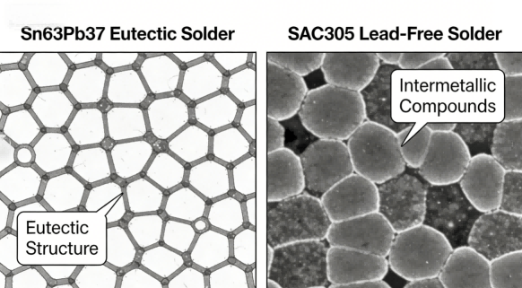
Hcjmpcba Lead Free Solder Comparison Diagram Of Microstructures Of Sn63pb37 And Sac305 Solders
The most critical difference between leaded vs lead free solder lies in thermal behavior.
Lead-free alloys require higher processing temperatures.
| Alloy | Melting Temperature | Typical Reflow Peak |
|---|---|---|
| Sn63Pb37 | 183°C | 210°C |
| SAC305 | 217–220°C | 240–250°C |
| SnCu | 227°C | 245–255°C |
Because lead-free solder melts at higher temperatures, PCB manufacturers must design thermal profiles carefully to avoid:
Component warpage
PCB delamination
Flux degradation
Void formation
At HCJMPCBA, the standard reflow profile for SAC305 uses:
Peak temperature: 245°C ±5°C
This is validated under Method #722-B thermal profile protocol.
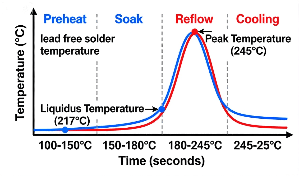
Hcjmpcba Lead Free Solder Reflow Soldering Temperature Profile Chart
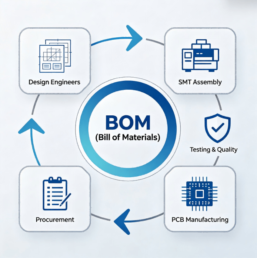
Industrial PCB assembly differs dramatically from manual soldering.
Below is the standard production workflow used in high-volume SMT manufacturing.
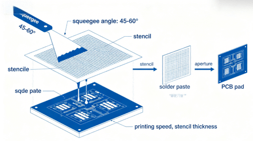
Stencil thickness and aperture design determine paste volume.
Key factors:
stencil thickness 0.12–0.15 mm
laser-cut stencil
Type 3 or Type 4 solder paste
Pick-and-place machines position components with ±30 µm accuracy.
Modern systems can place:
50,000+ components per hour
Boards pass through multiple heating zones:
1.Preheat
2.Thermal soak
3.Reflow peak
4.Controlled cooling
Proper lead free soldering temperature control ensures strong intermetallic bonding.
AOI detects:
insufficient solder
bridging
tombstoning
misalignment
Critical for:
BGA
QFN
hidden joints
To support OEM mass production, HCJMPCBA implements strict engineering control systems.
Each process document is controlled using:
Method ID: HCJ-SMT-722
Revision: B
Process Owner: Manufacturing Engineering
This ensures production consistency across batches.
Pilot production follows AQL sampling plans:
| Inspection Level | AQL |
|---|---|
| Critical defects | 0.65 |
| Major defects | 1.0 |
| Minor defects | 2.5 |
Reliability testing includes:
thermal cycling −40°C to +125°C
vibration testing
humidity testing
These tests compare lead solder vs lead free solder reliability under real-world stress conditions.
Every board manufactured by HCJMPCBA is traceable.
Traceability includes:
solder paste batch
PCB lot number
component reel ID
production date
operator ID
This allows customers to trace issues down to individual solder wire batches.
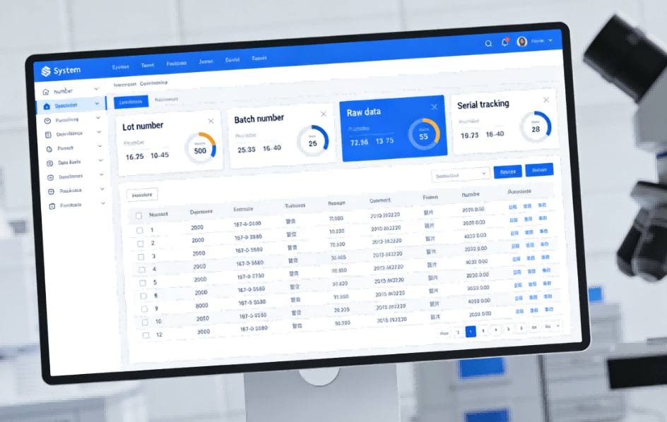
Hcjmpcba Lead Free Solder Mes System Traceability
OEM buyers often ask how to verify PCBA solder quality.
Below is the engineering evidence you can request.
| Evidence | Purpose |
|---|---|
| Method number + revision | Process control |
| Sample plan | Production qualification |
| Test conditions | Thermal reliability |
| Raw data | Inspection verification |
| Traceability | Batch accountability |
Purchasing teams may include the following clause in contracts:
All PCB assemblies must comply with IPC-A-610 Class 2 or Class 3 standards.
Supplier must provide solder alloy certification, process documentation,
traceability records, and inspection reports for each production batch.
Even experienced manufacturers encounter issues when switching from lead solder to lead free soldering.
Five common failures include:
1.Tin Whiskers
Microscopic conductive filaments caused by stress in tin coatings.
2.Voiding
Gas trapped in solder joints during reflow.
3.Tombstoning
Small components standing upright due to uneven wetting forces.
4.Insufficient Wetting
Poor solder flow due to oxidation or improper flux.
5.Mixed Alloy Contamination
Mixing leaded vs unleaded solder alloys reduces reliability.
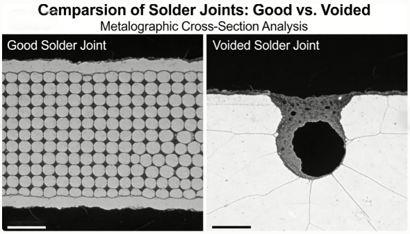
Hcjmpcba Lead Free Solder Comparison Diagram Of Metallographic Sections Of Weld Spots
Different industries require different solder strategies.
Medical electronics
high reliability
extended lifetime
IPC Class 3
Consumer electronics
cost optimized
high-volume SMT
SAC305 lead-free alloys
HCJMPCBA supports both environments by adjusting:
solder alloys
thermal profiles
inspection criteria
Q:What is solder made of?
A:Most electronic solder is an alloy based on tin combined with elements such as lead, silver, copper, or bismuth.
Q:What is the difference between lead solder and lead free solder?
A:Lead solder contains tin and lead, while lead free solder replaces lead with metals like silver and copper to comply with environmental regulations.
Q:What is the melting point of lead free solder?
A:Most SAC alloys melt around 217–220°C, about 34°C higher than traditional tin-lead solder.
Q:Can lead and lead free solder be mixed?
A:Mixing alloys is strongly discouraged because it alters melting behavior and joint reliability.
Q:What tools are required to solder circuit boards?
A:Typical soldering tools for circuit boards include:
solder paste printer
reflow oven
soldering iron
AOI inspection systems
Q:Why does lead-free solder look dull?
A:Unlike SnPb solder, lead-free alloys often appear matte after solidification due to different microstructures.
When selecting a PCB assembly partner, buyers should request:
solder alloy certification
reflow temperature profiles
inspection reports
reliability test data
batch traceability records
These documents significantly reduce procurement risk.
Understanding what solder is made of is essential for designing reliable electronic products. Modern electronics manufacturing has transitioned from traditional SnPb alloys to lead free solder materials such as SAC305, which provide environmentally compliant and mechanically robust solder joints.
However, solder alloy selection alone does not guarantee reliability. Consistent PCBA production requires:
controlled thermal profiles
standardized manufacturing methods
rigorous inspection procedures
full traceability across materials and batches
At HCJMPCBA, these principles form the foundation of every production run.
For more information about PCBA services, please contact Guangzhou Huachuang Precision Technology(HCJMPCBA).
Update triggers: standard revision changes / recurring questions / production checklist updates.
Discharging capacitors is a critical safety and quality control step in electronics and PCBA work. T
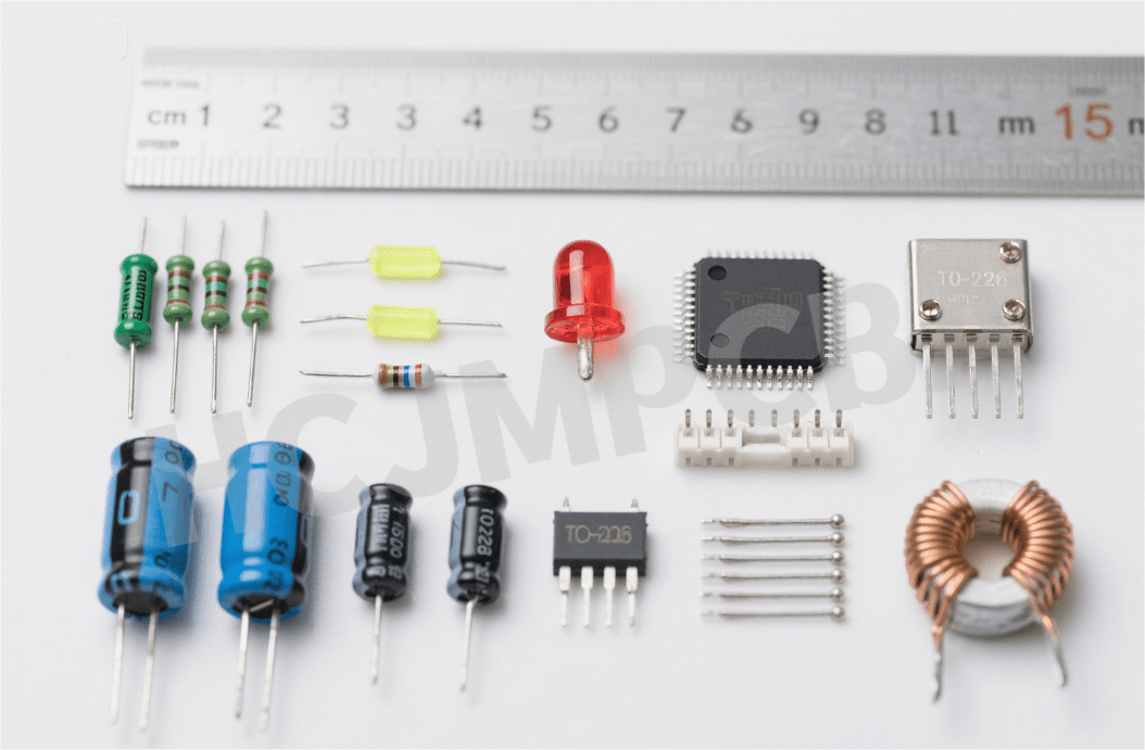
Electronic devices serve as the foundational elements of modern electronics—from simple sensors to
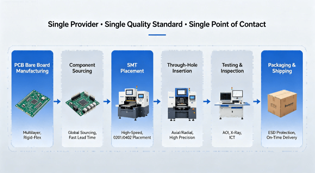
Full-service PCB manufacturing streamlines your supply chain from bare board fabrication to assemble