15 Expert Insights: What Does a Flame Sensor Do? How It Works & PCBA Integration Mastery
A flame sensor is a critical safety device that detects flame presence to prevent gas leaks and expl
Table of Contents
ToggleIn electronics manufacturing, electrical testing of printed circuit board assemblies (PCBAs) is a critical gatekeeping step. It catches manufacturing defects — open circuits, short circuits, incorrect component values, reversed polarity, and abnormal resistance or capacitance — before they reach the customer.
Among the various electrical testing solutions available, In-Circuit Testing (ICT) and Flying Probe Testing (FPT) are the two most widely adopted methods. Both are designed to detect common manufacturing defects, but they differ fundamentally in working principles, cost structures, application scenarios, and flexibility.
Understanding these differences is essential for hardware engineers and procurement teams making testing decisions that balance quality, cost, and time-to-market.
At Guangzhou Huachuang Precision Technology Co., Ltd. (HCJMPCBA), we offer both ICT and flying probe testing capabilities as part of our comprehensive PCBA services. With nearly 3,500 m² of ESD‑protected manufacturing space, multiple high-speed SMT lines, and ISO9001 and ISO13485 certifications, we help customers select and implement the right test strategy for each project — from prototype to mass production.
ICT is a fixed-fixture electrical testing method that uses a custom-designed bed-of-nails fixture to make simultaneous contact with predefined test points on a PCBA. The fixture contains precision spring-loaded probes that align with the circuit nodes of the target board.
Once the fixture is installed, the ICT system applies electrical signals, measures component parameters individually, and verifies the integrity of each solder joint and discrete component. ICT can perform not only basic electrical tests but also partial digital logic function verification, on-board FPGA configuration checks, and LED color and brightness validation.
Ultra-fast test speed: Simultaneous contact with all test points drastically shortens the single-board test cycle — typically 30–60 seconds per unit.
Low per-unit cost: After the initial fixture investment, the marginal cost of testing each additional board is extremely low.
Comprehensive component verification: Supports independent testing of resistors, capacitors, inductors, integrated circuits, and logic devices.
Stable mass production performance: Suitable for long-term, high-volume continuous manufacturing with consistent test results.
High upfront costs: Custom fixture design and manufacturing involve significant NRE (non-recurring engineering) expenses. A typical ICT fixture costs $5,000 to $50,000, depending on board complexity.
Long development lead time: Fixture production and program debugging typically take 4 to 8 weeks. Some sources report up to six weeks for fixture manufacture and programming.
Poor flexibility: Any PCB design modification may require fixture rework or replacement, increasing time and cost. A design change usually forces a new fixture.
Test point dependency: ICT requires dedicated test pads on the PCB layout. For highly dense boards with limited accessible nodes, fixture design becomes difficult or impossible.
Flying Probe Testing is a fixtureless testing technology that uses 4 to 20 high-precision, electrically controlled movable probes to sequentially “fly” to test points on both sides of a PCBA. Guided by CAD data and dedicated test programs, the probes accurately contact component pins, bond pads, or vias to perform electrical measurements — without any custom mechanical jigs.
No fixture costs: Eliminates the significant NRE expense of custom ICT fixtures. The upfront investment is minimal compared to ICT.
Fast setup: Programming time is typically under a week. Changeover between board revisions is rapid.
Design change flexibility: FPT adapts easily to frequent PCB revisions without requiring new fixtures. This makes it ideal for iterative development.
Access to dense boards: Flying probes can hit small targets in highly populated PCBAs that may be inaccessible to fixed test pins. Advanced FPT systems can probe test points even when no actual test pads exist.
Comprehensive coverage: FPT can test for opens, shorts, resistance, capacitance, polarity errors, micro-shorts, and phase differences. Most systems also include optical cameras for component polarity inspection.
Slower per-board test speed: Sequential probe movement means longer test cycles — typically 10–20 minutes per board. For high volumes, this becomes a bottleneck.
Higher per-unit cost at scale: The extended test time makes FPT less cost-effective in mass production. At $90/hour, a 20-minute test costs $30 per board.
Not suitable for high-volume: FPT is ideal for prototypes and low-to-medium volumes, but cannot match ICT’s throughput for production runs of thousands of units per day.
| Factor | ICT (Bed-of-Nails) | Flying Probe |
|---|---|---|
| Test principle | Simultaneous contact via fixed fixture | Sequential contact via movable probes |
| Fixture requirement | Custom bed-of-nails fixture required | No fixture required |
| Fixture cost | $5,000 – $50,000 (one-time NRE) | $0 |
| Fixture lead time | 4 – 8 weeks | Not applicable |
| Test time per board | 30 – 60 seconds | 10 – 20 minutes |
| Per-unit test cost at volume | Very low (pennies per board) | Higher ($30+ per board at scale) |
| Design change adaptability | Poor — requires new fixture | Excellent — software update only |
| Ideal production volume | High-volume (thousands+ per day) | Prototype, pilot, low-to-mid volume |
| Best for | Mature, stable designs in mass production | NPI, design iterations, complex/dense boards |
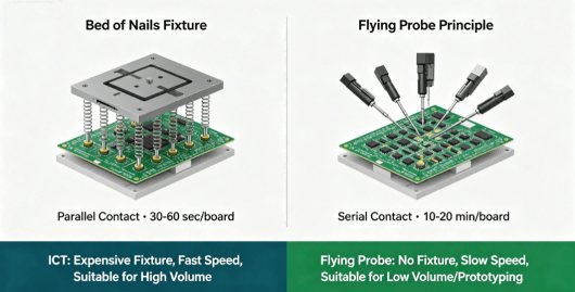
Comparison Diagram Of Ict And Flying Probe Testing Principles
ICT is the right choice when:
Production volume is high — typically thousands of boards per day or more. The high upfront fixture cost is amortized over a large number of units, driving per-unit test cost to pennies.
The design is mature and stable — with few expected revisions. Once the fixture is built and validated, it can run for years without change.
Test speed is critical — 30–60 seconds per board enables inline testing that keeps pace with high-speed SMT production lines.
Comprehensive component-level verification is required — ICT can independently test each component on the board.
For a product in steady-state mass production — say, 10,000 units per month with no design changes anticipated — ICT offers the lowest total cost of ownership despite the significant upfront investment.
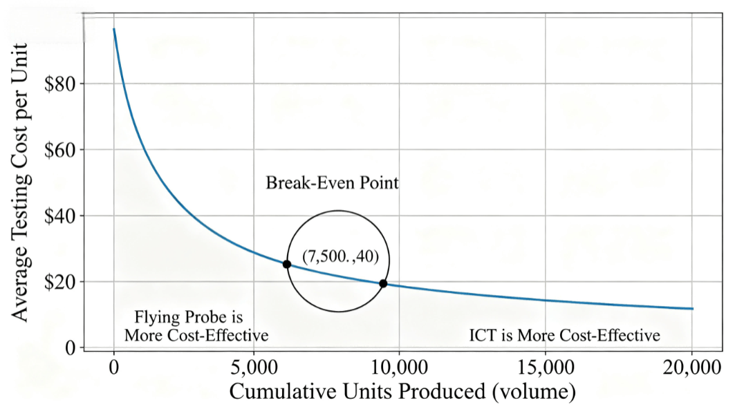
Relationship Diagram Between Ict Fixture Cost And Output
Flying Probe Testing is the right choice when:
Production volume is low — prototypes, pilot runs, or small-batch production (typically under 500–1,000 units). With no fixture cost, FPT avoids the prohibitive per-board burden of ICT fixture amortization.
The design is still evolving — during NPI (new product introduction) or when multiple design iterations are expected. FPT adapts to changes with a simple software update, no fixture rework required.
The board is highly dense or complex — with limited space for test pads. Flying probes can access small targets that fixed ICT pins cannot reach.
Time-to-market is critical — FPT can be set up in days, while ICT fixture development takes weeks.
For an R&D team running 50 prototype boards through three design spins, flying probe testing is not just more economical — it is often the only practical option.
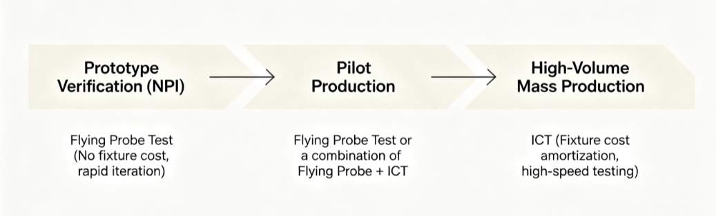
Test Strategy Selection Diagram In The Product Life Cycle
For many production scenarios, the optimal solution is not an either/or choice but a combined test strategy.
A common pattern: use flying probe testing during NPI and early prototype phases, where design changes are frequent and volumes are low. Once the design stabilizes and production ramps up, transition to ICT for high-speed, low-cost testing at volume.
Some manufacturers also use flying probe as a complementary test method alongside ICT — for example, using ICT for high-speed screening of common defects and flying probe for deeper diagnostic testing of specific nodes that the ICT fixture cannot access.
At HCJMPCBA, we help customers design and implement the right test strategy for each phase of their product lifecycle. Our capabilities include both ICT (with custom fixture development) and flying probe testing, allowing seamless transition from prototype to production without changing test partners.
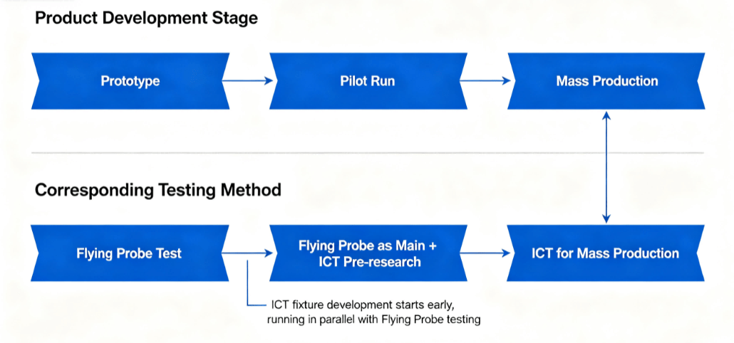
Flow Chart Of Combined Test Strategy For Ict And Flying Probe
Both ICT and flying probe perform what is called manufacturing defects analysis (MDA) — they detect the most common process faults that occur during PCB assembly.
However, there are differences in coverage:
ICT offers comprehensive component-level testing, including independent verification of resistors, capacitors, inductors, ICs, and logic devices. It can also perform limited functional checks like LED color validation.
Flying Probe can test for opens, shorts, resistance, capacitance, inductance, polarity errors, micro-shorts, and phase differences. Many FPT systems include optical cameras for automatic component polarity inspection, adding coverage for components that cannot be accessed electrically.
For most PCBA applications, both methods provide adequate coverage for manufacturing defect detection. The choice is driven primarily by volume, cost, and flexibility requirements rather than by test coverage differences.
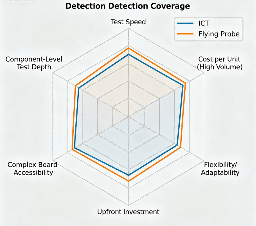
Radar Chart For Comparison Of Defect Detection Coverage Rate
At Guangzhou Huachuang Precision Technology Co., Ltd. (HCJMPCBA), we understand that testing strategy is not a one-size-fits-all decision. Different projects — at different stages of development and different volumes — require different approaches.
Our testing capabilities include:
Flying Probe Testing — Ideal for prototypes, NPI, and low-volume production. Fast setup, no fixture costs, and full flexibility for design changes.
ICT (In-Circuit Testing) — For high-volume production runs. Custom fixture development, 30–60 second test cycles, and comprehensive component-level verification.
Combined Test Strategies — We help customers plan the transition from flying probe during development to ICT at production ramp, ensuring seamless continuity.
With nearly 3,500 m² of ESD‑protected manufacturing space, multiple high-speed SMT lines, and ISO9001 and ISO13485 certifications, we provide the manufacturing capacity and quality systems to support your project from first prototype to full-scale production — tens of thousands of boards per month.
Our engineering team provides upfront test strategy recommendations based on your board complexity, production volume, and development timeline. We handle fixture development for ICT, program generation for flying probe, and full test documentation — so your engineering team can focus on design, not test logistics.
A flame sensor is a critical safety device that detects flame presence to prevent gas leaks and expl
Learn the complete pcb manufacturing process in a clear, step-by-step way—from design review (DFM)
A budgetary quote is a preliminary cost estimate used during early PCBA development to assess feasib