HCJMPCBA’s Guide: What Is SMT Manufacturing? Uncover 7 Key Steps & Supplier Selection Secrets for Flawless PCBAs
Surface Mount Technology (SMT) lies at the heart of modern electronics assembly, enabling ever‑sma
Advantages of PCB Components: 10 Essential Benefits and How to Select the Right Parts
Table of Contents
TogglePCB components are electronic parts mounted on or connected to a printed circuit board to perform functions such as power regulation, signal processing, switching, sensing, and communication. Selecting suitable components improves electrical performance, reliability, thermal management, and manufacturability while reducing assembly defects, redesign costs, and production delays.
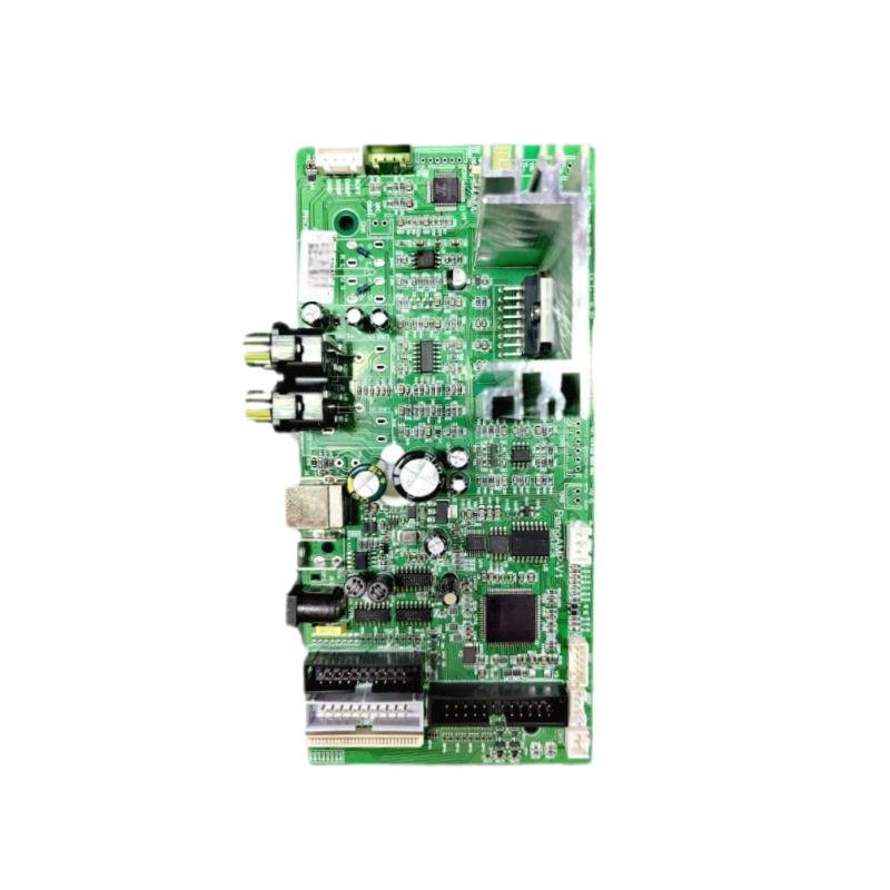
A printed circuit board (PCB) provides the conductive pathways that connect electronic components. Once components are mounted and interconnected through an assembly process, the resulting assembly is commonly called a printed circuit board assembly (PCBA).
The selection of circuit board components affects more than circuit functionality. Package dimensions, electrical tolerances, operating temperatures, component availability, and soldering requirements can all influence the final product’s performance and manufacturing cost.
For engineering teams and purchasing professionals, understanding these factors is essential when moving from a prototype to repeatable volume production.
A typical circuit board components list includes passive components, active semiconductors, electromechanical devices, sensors, and timing or communication components. Their functions differ, so each category requires specific selection criteria.
Resistors control current, divide voltage, and establish signal bias. Important parameters include resistance, tolerance, rated power, and temperature coefficient. A resistor with the correct resistance value may still be unsuitable if its power rating is insufficient.
Capacitors support filtering, decoupling, coupling, and energy storage. Selection should consider capacitance, rated voltage, equivalent series resistance (ESR), temperature characteristics, and effective capacitance under operating bias.
Inductors store energy in magnetic fields and are widely used in power converters and filters. Inductance, saturation current, rated current, and DC resistance influence performance and heat generation.
Integrated circuits (ICs) perform processing, control, amplification, memory, and power management. Engineers must verify the complete manufacturer part number, package, pinout, operating limits, and interface requirements.
IC packages such as BGA and QFN can also affect soldering, inspection, and test accessibility.
Transistors and diodes perform switching, amplification, rectification, and circuit protection. Their voltage, current, power dissipation, thermal limits, and polarity must match the application.
Connectors, switches, relays, and fuses provide electrical interfaces, switching functions, and circuit protection. Their selection involves current ratings, contact resistance, mechanical strength, mating compatibility, mounting method, and service life.
Sensors measure physical conditions such as temperature, pressure, or light. Oscillators provide timing references, while communication components support wired or wireless interfaces.
These electronic circuit board components may require additional attention to calibration, signal integrity, environmental conditions, and system-level compatibility.
| Component | Primary function | Key selection parameters | Common risk |
|---|---|---|---|
| Resistor | Current limiting and voltage division | Resistance, tolerance, power | Overheating |
| Capacitor | Filtering and energy storage | Capacitance, voltage, ESR | Insufficient effective capacitance |
| Inductor | Energy storage and filtering | Inductance, saturation current | Magnetic saturation |
| IC | Processing and control | Part number, package, operating range | Pinout or footprint mismatch |
| Diode | Rectification and protection | Reverse voltage, current | Incorrect polarity |
| MOSFET | Electronic switching | Voltage, current, RDS(on), thermal limits | Excessive power loss |
| Connector | Electrical interconnection | Pitch, current, mating interface | Mechanical incompatibility |
| Sensor | Physical measurement | Range, accuracy, interface | Incorrect readings |
| Oscillator | Clock generation | Frequency, stability | Timing errors |
| Fuse | Overcurrent protection | Current rating, breaking capacity | Inadequate fault protection |
This PCB parts list is a starting point rather than a universal specification. The correct component set depends on circuit architecture, intended use, operating conditions, and applicable product requirements.
The advantages of PCB components become most apparent when suitable devices are selected and integrated into a well-designed circuit.
Modern surface-mount components allow many functions to fit into a relatively small PCB area. Smaller packages and integrated circuits can reduce product dimensions and support lightweight electronic equipment.
However, higher component density can make heat dissipation, inspection, and rework more difficult. Compactness should therefore be balanced against manufacturing capability and maintenance requirements.
Appropriately selected components help circuits meet their electrical requirements. Decoupling capacitors, filters, precision resistors, and suitable interface devices can support stable power delivery and signal quality.
The result depends on component characteristics, PCB layout, grounding, routing, and operating conditions. A high-performance component cannot compensate for every circuit-design problem.
Integrated circuits combine multiple electronic functions in one package. This can reduce the number of discrete parts, simplify circuit connections, and support more sophisticated control systems.
The trade-off is that highly integrated devices may have more complex sourcing, programming, thermal, and replacement requirements.
Low-power ICs, efficient power-management devices, and appropriately selected MOSFETs can reduce energy losses.
Engineers should evaluate actual load conditions, switching frequency, conduction losses, and thermal performance instead of relying only on headline efficiency figures.
Suitable voltage, current, temperature, and power margins help components operate within their specified limits. Appropriate component selection also reduces exposure to foreseeable environmental and electrical stresses.
Nevertheless, product reliability depends on the complete system, including PCB design, solder joints, assembly quality, operating conditions, and maintenance practices.
Standardized packages, clearly identified manufacturer part numbers, and controlled BOM revisions help production teams assemble the correct components consistently.
This becomes particularly important when a product transitions from prototype builds to volume production. Clear documentation reduces the risk of unapproved substitutions and discrepancies between engineering and manufacturing files.
Selecting components with suitable power ratings, thermal characteristics, and package designs helps manage heat generation.
Engineers should consider power dissipation, thermal resistance, copper area, airflow, and nearby heat sources. Replacing one component with a higher-rated part does not necessarily solve a board-level thermal problem.
Different component specifications and functional devices allow designers to adapt circuit boards to medical equipment, industrial controllers, communication devices, and consumer electronics.
Flexibility is most useful when component changes are evaluated against the original electrical, mechanical, software, and compliance requirements.
Test points, accessible interfaces, and appropriate component placement can make circuit verification and fault isolation more efficient.
Depending on the design, inspection may involve automated optical inspection (AOI), X-ray inspection, in-circuit testing (ICT), or functional testing. Each method serves a different purpose.
Selecting components with stable supply, documented specifications, and suitable lifecycle status helps reduce procurement uncertainty.
An approved alternative may improve supply resilience, but it should not be treated as automatically interchangeable. Electrical characteristics, package, pinout, thermal behavior, and assembly requirements must be reviewed before substitution.
Circuit board components support a wide range of electronic devices. Their selection priorities vary according to product function and operating environment.
| Application | Typical components | Main selection priorities |
|---|---|---|
| Medical electronics | Sensors, ICs, power components | Reliability, documentation, intended-use requirements |
| Industrial control | Relays, MOSFETs, controllers | Environmental conditions, electrical robustness |
| AI and computing | Processors, memory, power-management ICs | Thermal performance, power delivery, signal integrity |
| Consumer electronics | MCUs, sensors, wireless modules | Size, power consumption, cost |
| Automotive electronics | Controllers, sensors, power semiconductors | Applicable qualification and environmental requirements |
| Communication equipment | RF devices, filters, oscillators | Frequency response and signal integrity |
These examples illustrate common circuit boards applications and uses in electronic devices, not universal component requirements. Actual specifications depend on the product’s intended use, operating environment, customer requirements, and applicable regulations.
A structured selection process helps engineers identify component risks before they become assembly defects, supply interruptions, or costly redesigns.
Document operating temperature, humidity, voltage, current, load conditions, vibration exposure, and expected service life.
Evidence to retain: Product requirements, environmental specifications, and critical-parameter lists.
Check minimum and maximum operating parameters, tolerance, rated power, temperature drift, and relevant derating requirements.
Design margins should reflect the component datasheet, actual application conditions, and product risk rather than an arbitrary percentage applied to every component.
Evidence to retain: Manufacturer datasheets, engineering calculations, and design-review records.
Confirm package dimensions, PCB land pattern, pin assignments, orientation, component height, and available mechanical clearance.
Two components with similar electrical specifications may still have different pinouts or footprints.
Evidence to retain: Controlled BOM, package drawings, PCB library information, and assembly documentation.
Assess power dissipation, thermal resistance, heat paths, mechanical loading, and potential vibration-related risks.
Large connectors and heavy components may require particular attention to mechanical support and solder-joint stress.
Evidence to retain: Thermal assessments, mechanical reviews, and applicable test results.
Check lifecycle status, lead times, purchasing channels, and the availability of approved alternatives.
For critical components, procurement records and lot information can support investigations into sourcing discrepancies.
Evidence to retain: Manufacturer information, purchasing records, and approved alternate-part lists.
Determine whether the component is suitable for the intended SMT or through-hole process. Review package-specific soldering limits, moisture sensitivity, storage conditions, and floor-life requirements where applicable.
IPC/JEDEC J-STD-033 addresses handling, packing, shipping, and use of moisture- and reflow-sensitive devices. Following the applicable requirements helps reduce risks associated with moisture exposure during assembly.
Evidence to retain: Datasheets, moisture-sensitivity information, and applicable process records.
Design for Manufacturability (DFM) and Design for Testability (DFT) reviews help identify problems before assembly begins.
Review component spacing, solderability, inspection accessibility, test-point locations, and the feasibility of rework.
At HCJMPCBA, engineering feedback can be incorporated into project preparation according to the agreed scope and the information supplied by the customer.
Evidence to retain: Engineering review comments, issue lists, and customer-approved resolutions.
A production-ready BOM should identify the manufacturer, complete manufacturer part number, package, reference designator, quantity, and applicable revision.
Alternative parts should undergo documented technical review and approval before implementation. Similar nominal values alone do not establish equivalence.
Evidence to retain: Controlled BOM, alternate-part assessment, and engineering change approvals.
Select verification methods according to component type, package, product risk, and customer requirements.
These methods are complementary rather than interchangeable. Their suitability and coverage depend on the board design and test requirements.
Evidence to retain: Inspection plans, test procedures, acceptance limits, and test records.
Before volume production, confirm the sample’s BOM revision, assembly documentation, inspection scope, test conditions, and acceptance criteria.
Record test results and resolve identified nonconformities. Once the required approvals are complete, release the agreed configuration for production.
Subsequent changes to components, firmware, process settings, or test methods should follow the agreed change-control procedure.
Evidence to retain: Sample approval records, relevant test data, production-release documentation, and change history.
The lowest-priced component is not necessarily the lowest-cost option over the product lifecycle. A useful decision considers technical suitability, assembly risk, supply continuity, and the consequences of failure.
| Decision factor | Option A | Option B | Recommended evaluation |
|---|---|---|---|
| Package | Smaller package | Larger package | Compare space, thermal limits, assembly capability, and inspection needs |
| Tolerance | Tighter tolerance | Standard tolerance | Select according to circuit requirements |
| Lifecycle | Active product | NRND or obsolete product | Evaluate future supply and redesign risk |
| Sourcing | Single source | Approved alternative available | Balance supply resilience and technical consistency |
| Unit price | Lower price | Higher-rated or better-documented part | Compare total risk and lifecycle cost |
| Testability | Limited access | Suitable test points | Consider test coverage and fault isolation |
For purchasing teams, total cost may include component price, assembly losses, rework, testing, delays, and redesign. The appropriate choice is the option that meets the technical requirements while keeping overall production risk acceptable.
Component selection becomes a manufacturing issue when engineering files, purchased materials, assembly processes, and acceptance criteria are not aligned.
HCJMPCBA, operated by Guangzhou Huachuang Precision Technology, approaches PCBA manufacturing through project-specific engineering review, assembly preparation, inspection, testing, and production documentation.
Depending on the agreed scope, project preparation may include BOM and revision checks, package and polarity review, DFM/DFT feedback, alternate-part confirmation, and assessment of inspection or test requirements.
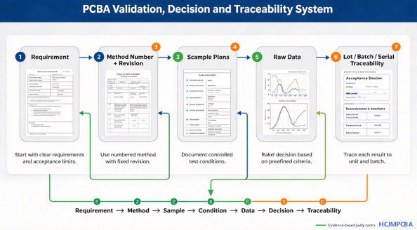
| Control item | What should be defined | Why it matters |
|---|---|---|
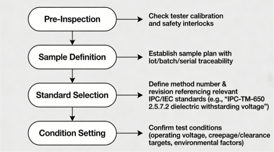
| Method number + revision | Applicable inspection or test method and revision | Supports consistent execution |
| Sample plan | Sample size, frequency, and acceptance rules | Defines the scope of verification |
| Test conditions | Relevant voltage, load, temperature, operating mode, and setup | Makes results interpretable |
| Raw data | Measured values and relevant test-system records | Supports investigation beyond pass/fail |
| Traceability | Agreed lot, batch, or serial identifiers | Helps contain and investigate quality issues |
These controls should be established before production whenever they are relevant to the project.
Method number + revision: A statement such as “tested according to standard” may be insufficient when several methods or revisions are possible. The applicable method and revision should be identified in the agreed documentation.
Sample plan: Define the sample quantity, inspection frequency, and acceptance rules rather than relying on an undefined statement that sampling was performed.
Test conditions: A PASS result is meaningful only in relation to the conditions and acceptance limits under which the test was performed.
Raw data: Agree on which measurements, images, logs, and instrument records must be retained or delivered.
Traceability: Determine whether the project requires component-lot, production-batch, or individual-serial-number tracking. The required level should match the product’s risk and contractual requirements.
A controlled PCBA workflow may follow this sequence:
Engineering Review → BOM and Revision Confirmation → Component Verification → Assembly → Inspection → Testing → Sample Approval → Production Release → Record Retention
HCJMPCBA can evaluate suitable assembly and verification arrangements according to the board design, production requirements, and agreed quality plan. Relevant capabilities may include SMT and through-hole assembly, 3D SPI, AOI, X-ray inspection for applicable packages, and electrical or functional testing where specified.
Not every project requires every inspection method. The objective is to establish appropriate controls and evidence for the actual product, rather than simply maximize the number of inspections.
Verification should connect each requirement to an appropriate method, acceptance basis, and retained record.
| Verification item | Method | Acceptance basis | Evidence |
|---|---|---|---|
| Component identity | BOM and marking review | Approved part number and revision | BOM and applicable receiving records |
| Component placement | AOI or visual inspection | Approved assembly documentation | Inspection records |
| Solder-paste printing | SPI, where specified | Defined process limits | SPI results |
| Hidden solder joints | X-ray, where appropriate | Agreed acceptance criteria | Images and inspection results |
| Electrical performance | ICT or specified electrical test | Approved test limits | Test results and relevant measurements |
| Functional performance | Functional test | Approved functional specification | Test conditions and results |
| Traceability | Lot, batch, or serial tracking | Defined traceability scope | Traceability records |
| Engineering changes | Revision and approval review | Approved document revision | Change history |
IPC-A-610 provides acceptance criteria for electronic assemblies, while IEC 61191-1 addresses requirements and verification criteria for soldered electrical and electronic assemblies using surface-mount and related technologies. The applicable editions and contractual requirements should be confirmed for each project.
Neither a visual acceptance standard nor an inspection-machine result automatically proves that a completed PCBA meets every functional or long-term reliability requirement. Those claims require appropriate additional verification.
The following clause can be adapted for an RFQ, purchase specification, or manufacturing quality agreement.
- All components shall conform to the customer-approved BOM, including manufacturer part numbers, package specifications, and applicable document revisions.
- No component substitution shall be implemented without documented technical review and approval by the designated customer authority.
- Inspection and testing shall follow the agreed method number and revision, sample plan, test conditions, and acceptance criteria.
- Test records, including applicable raw data, shall be retained and provided in accordance with the agreed quality plan and contractual requirements.
- Component and assembly traceability shall be maintained to the agreed lot, batch, or serial-number level, as applicable.
A low purchase price may be offset by supply instability, poor suitability, or additional verification costs. Evaluate lifecycle and total production risk.
Similar electrical ratings do not guarantee compatible dimensions, pinouts, or soldering requirements. Verify the manufacturer’s package documentation.
Differences in thermal performance, electrical characteristics, or pin assignments can make an apparently similar part unsuitable. Require documented assessment and approval.
A pass/fail result without a defined method, sample plan, and test conditions provides limited evidence. Establish the verification requirements before sample approval.
Uncontrolled changes can lead to incorrect components or inconsistent production configurations. Maintain approved revisions and appropriate traceability records.
Consider an industrial controller moving from prototype builds to volume production. Its BOM contains components with unstable lead times, an unapproved alternative power device, and incomplete functional-test records.
A structured response would include:
This approach helps reduce the risk of unauthorized substitution, unclear test results, and discrepancies between samples and production builds. It does not guarantee defect-free manufacturing, but it creates a more controlled basis for production decisions and subsequent investigations.
Additional verification may be appropriate when a project includes high-power components, hidden-joint packages, critical functions, uncertain supply sources, or newly approved alternatives.
It should also be considered when a new design enters production, a key component changes, a new purchasing source is introduced, recurring defects occur, or product requirements change.
The verification plan should be proportionate to the risk. Additional tests should address a defined concern rather than being added without a clear purpose.
Common circuit board components include resistors, capacitors, inductors, integrated circuits, diodes, transistors, connectors, sensors, oscillators, and protection devices. The exact component list depends on the circuit’s function, operating environment, and design requirements.
A PCB is a printed circuit board containing conductive pathways and component mounting features. A PCBA is an assembled board with electronic components mounted and interconnected. PCB fabrication and PCBA assembly are related but distinct manufacturing processes.
Start with functional and electrical requirements, then evaluate package compatibility, thermal performance, operating conditions, lifecycle, sourcing, assembly constraints, and testability. Confirm critical decisions against manufacturer datasheets and the approved design documentation.
A useful PCB parts list includes manufacturer name, complete part number, reference designator, quantity, package, key specifications, approved alternatives, and the applicable BOM revision. Additional sourcing or traceability fields may be required for production.
Not automatically. Package dimensions, pinout, tolerance, thermal behavior, frequency response, and soldering limits may differ. Evaluate the proposed alternative against the original requirements and obtain the necessary engineering approval before implementation.
Depending on the product, verification may include incoming-material checks, SPI, AOI, X-ray, ICT, and functional testing. Each method addresses different risks, so the test plan should reflect component packages, circuit design, acceptance criteria, and customer requirements.
Component and assembly inspection checks matters such as identity, placement, polarity, and solder-joint acceptability. Functional testing evaluates whether the assembly performs its intended functions under defined conditions. Neither necessarily replaces the other.
Depending on the agreement, useful evidence includes the controlled BOM, engineering review records, sample approval, inspection and test plans, method numbers and revisions, defined test conditions, relevant raw data, and agreed lot, batch, or serial-number traceability records.
A supplier evaluation should focus on whether the manufacturing process can meet the project’s documented requirements.
Before production, request:
During sample validation, request:
Before and during volume production, agree on:
Not every customer needs unrestricted copies of every manufacturing record. The scope of record delivery, confidentiality, retention periods, and access rights should be established before production.
Selecting the right components is an important first step, but consistent manufacturing also requires controlled documentation, suitable assembly processes, and clearly defined verification criteria.
HCJMPCBA supports PCB assembly projects through project-specific engineering review, SMT and through-hole assembly, applicable inspection processes, and testing arrangements based on agreed requirements. For projects moving from prototypes to volume production, the goal is to align the approved BOM, assembly documentation, verification plan, and production records before release.
Customers preparing a new PCBA project can begin by providing the Gerber files, BOM, assembly drawings, expected volume, critical component requirements, and test specifications. This information helps establish the scope of engineering review and identify questions that should be resolved before production.
Update triggers: standard revision changes / recurring questions / production checklist updates.
Surface Mount Technology (SMT) lies at the heart of modern electronics assembly, enabling ever‑sma
A comprehensive guide to hipot testing (high potential/hi-pot/dielectric withstand), explaining what
Comprehensive guide to what is ground in electrical circuits: Learn how to safely implement electric