15 Practical Insights Into Relays: What Does a Relay Do & How It Works in PCBA Design
This comprehensive guide explains relays, what a relay does, and how relays work in electronic and P

A ground circuit provides a safe, low-resistance return path for electrical current, preventing electric shock, equipment damage, and signal distortion. Proper electrical grounding ensures system stability and electromagnetic compatibility (EMC) by establishing a consistent zero-voltage reference point across complex assemblies. This guide is maintained by the HCJMPCBA engineering team and updated with production checklists.
Stable Voltage Reference: Grounding establishes a reliable zero-potential baseline, ensuring clean signal transmission in sensitive microelectronic circuits.
Operator Safety & Fault Protection: Effective safety earthing diverts fault currents safely away from operators and into the earth, preventing lethal electrical shocks.
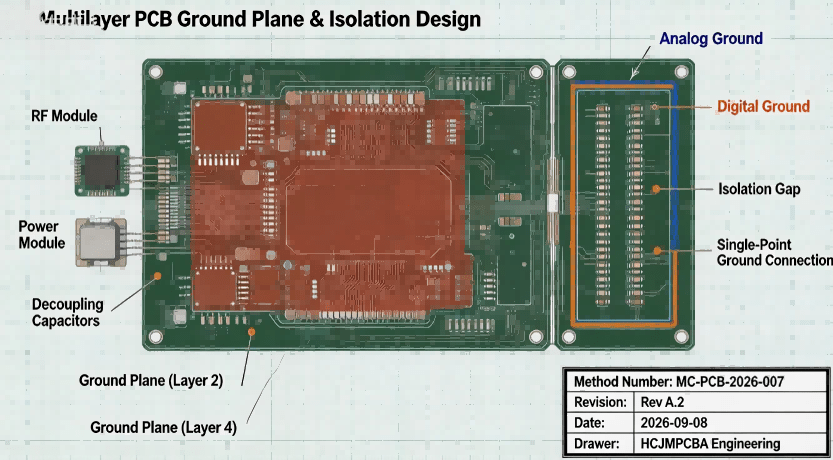
Noise Mitigation & EMI Control: Meticulous PCB ground plane design and proper ground wiring eliminate parasitic noise, grounding loops, and electromagnetic interference.
Evaluating a contract manufacturer for custom electronic production requires looking beyond basic component pricing. The matrix below contrasts standard low-cost board suppliers with a tier-1 precision manufacturing partner like HCJMPCBA.
| Evaluation Metric | Standard Low-Cost Board | Tier-1 Precision Grounding (HCJMPCBA) |
| Ground Plane Design | Basic copper pour; prone to grounding loops and EMI. | Optimized multi-layer ground stack-up with segregated analog/digital planes. |
| Sourcing & Materials | Uses generic terminal blocks and unverified copper wire. | Sources certified high-conductivity terminals and UL-approved wire harnesses. |
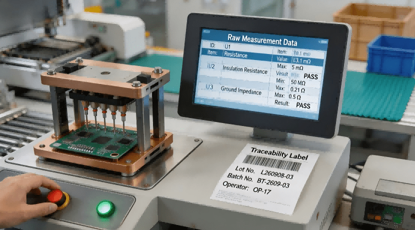
| Testing Protocols | Random visual checks; basic power-on verification. | 100% automated continuity, resistance, and high-voltage isolation testing. |
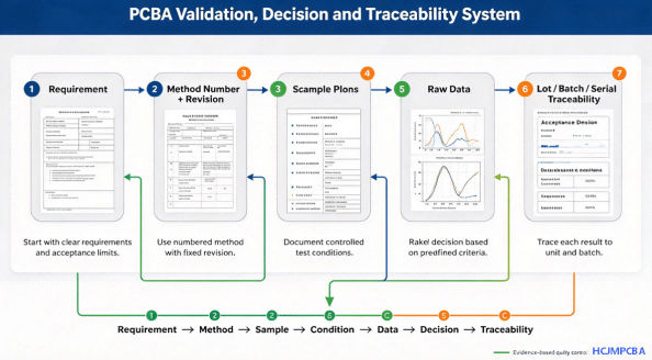
| Traceability | Minimal paper logs; loose batch identification. | Full end-to-end traceability (lot/batch/serial) from raw laminate to final boxed unit. |
Before any circuit board or wiring assembly enters production, our engineering team executes a comprehensive Design for Manufacturing (DFM) review. We analyze ground return paths, shielding requirements, and netlist connectivity, assigning a unique method number + revision code to every engineering change. This ensures that any layout modification is seamlessly tracked across all manufacturing lines.
Engineering Review & Revision Control
Sourcing robust grounding electrical components—such as ground studs, star washers, bonding straps, and high-purity copper wiring—is critical for field reliability. We deploy a structured sample plan that allows engineers to test mechanical fit, electrical resistance, and thermal endurance on prototype runs before committing to mass production.
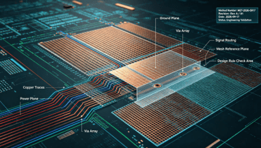
Achieving optimal electrical grounding begins at the PCB layout stage. We implement solid continuous ground planes on internal layers to minimize circuit inductance and provide low-impedance return paths. Special care is taken to avoid splitting planes underneath high-speed digital traces to prevent unwanted EMI radiation.
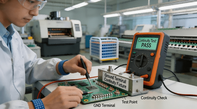
During assembly, technicians ensure that every ground connection is securely soldered or mechanically fastened without cold joints or high resistance. We perform rigorous in-process inspections to verify that chassis grounds, earth terminals, and internal logic grounds maintain uninterrupted electrical continuity.
Ground Connection
Quality assurance is never left to chance. Every completed assembly undergoes automated electrical verification under strict test conditions (such as controlled ambient temperatures and specified test currents). We log exact raw data metrics—including ground bond resistance and insulation breakdown thresholds—to guarantee absolute compliance.
Rigorous Testing & Raw Data Logging
| Test Parameter | Standard / Specification | Acceptance Criteria | Provided Evidence |
| Ground Continuity Resistance | IPC-A-610 / UL 508A | Resistance value $< 0.1\,\Omega$ between chassis and earth terminal. | Automated test log report (Raw Data) |
| Dielectric Withstand (Hipot) | IEC / UL standards | No breakdown under high test voltage (e.g., $1000\text{V}$ AC) for $1\text{ minute}$. | Dielectric test certificate |
| Ground Plane Impedance | IPC-2221 | Low-frequency and high-frequency return paths within design tolerance. | Network analyzer / impedance report |
| Mechanical Bond Integrity | IPC-WHMA-A-620 | Secure fastening without wire strand breakage or terminal loosening. | Pull-force and torque inspection sheet |
To eliminate supply chain ambiguity and protect your procurement interests, you can directly copy and paste the following quality assurance clause into your Purchase Orders:
“The supplier shall manufacture and assemble all electronic units in strict compliance with IPC and UL standards, ensuring proper electrical grounding and solid ground connection integrity. 100% automated continuity and resistance testing must be performed prior to shipment. The supplier is required to provide complete component lot/batch traceability documentation and raw test data logs with every delivery.”
Creating Ground Loops: Allowing multiple ground paths with slight potential differences creates circulating currents, introducing severe electromagnetic interference (EMI) into sensitive analog circuits.
Neglecting Ground Connection Continuity: Failing to ensure a low-resistance bond between metal enclosures and internal PCB ground points compromises safety earthing effectiveness.
Failing to Maintain Revision Control: Omitting a formal method number + revision tracking system during layout updates leads to outdated grounding topologies being manufactured.
Accepting Statistical Sampling for Safety Grounds: Relying on random batch sampling instead of 100% continuity testing for protective earth circuits introduces unacceptable safety risks.
Using Unverified Terminal Blocks for Ground Wiring: Installing low-quality, non-rated connectors for ground wiring can cause high contact resistance and catastrophic thermal failure under fault conditions.
Advanced electronic systems and high-density assemblies require flawless grounding architectures across multiple industries:
Industrial Automation Control Panels: Discharging static buildup and protecting high-voltage motor drives from electrical transients and noise.
Medical Diagnostic Equipment: Ensuring ultra-low leakage current and pristine signal acquisition for patient-connected monitoring devices.
Telecommunications Infrastructure: Maintaining stable reference planes and lightning surge protection for high-frequency data routers and base stations.
Automotive Power Electronics: Managing high-current return paths and shielding sensitive control ECUs inside electric vehicles (EVs).
Q1: What is ground in electronic circuits and why is it necessary?
A circuit ground serves as a common electrical reference point (zero-voltage baseline) and provides a safe return path for electrical currents, ensuring both stable signal processing and user safety against electrical shocks.
Q2: How do you ground a wire safely in a custom electronic assembly?
Safely grounding a wire involves stripping the insulation without damaging inner strands, crimping or soldering it to an approved terminal, and securing it to a designated, clean metallic chassis point or earth busbar using proper torque specifications.
Q3: What is the difference between signal ground and chassis ground?
Signal ground is the reference point for voltage and data signals within a circuit, whereas chassis ground connects the physical metallic enclosure of the device to the earth to protect operators from electrical faults.
Q4: What test conditions are required during ground continuity testing?
Continuity testing is typically performed using a low-test-current source (such as $100\text{mA}$ to $1\text{A}$) to measure DC resistance across bonding points, verifying that resistance remains well below acceptable thresholds (typically under $0.1\,\Omega$).
Q5: How does HCJMPCBA ensure end-to-end traceability (lot/batch/serial)?
We employ an advanced Manufacturing Execution System (MES) utilizing barcode scanning at every production stage. Every reel of wire, connector lot, and PCB laminate sheet is linked to a unique traveler document, enabling instant historical tracking.
Q6: Why is a pre-production sample plan essential for complex PCB layouts?
A structured sample plan allows engineers to validate thermal dissipation, signal integrity, and grounding performance on a small prototype batch, preventing costly design flaws before entering high-volume mass production.
When partnering with a premier manufacturing facility, you have the right to request comprehensive technical proof to verify quality claims. At HCJMPCBA, we routinely provide:
Automated electrical test reports containing exact raw data logs for continuity and resistance.
Third-party component certifications and RoHS/REACH material compliance documentation.
Crimp cross-section analysis and mechanical pull-test verification sheets.
Lot and batch traceability certificates linking finished assemblies directly to raw material suppliers.
For more information about PCBA services, please contact Guangzhou Huachuang Precision Technology (HCJMPCBA).
Update triggers: standard revision changes / recurring questions / production checklist updates.
This comprehensive guide explains relays, what a relay does, and how relays work in electronic and P
Learn pcb assembly best practices with our in‐depth guide on soldering circuit boards. Explore adv
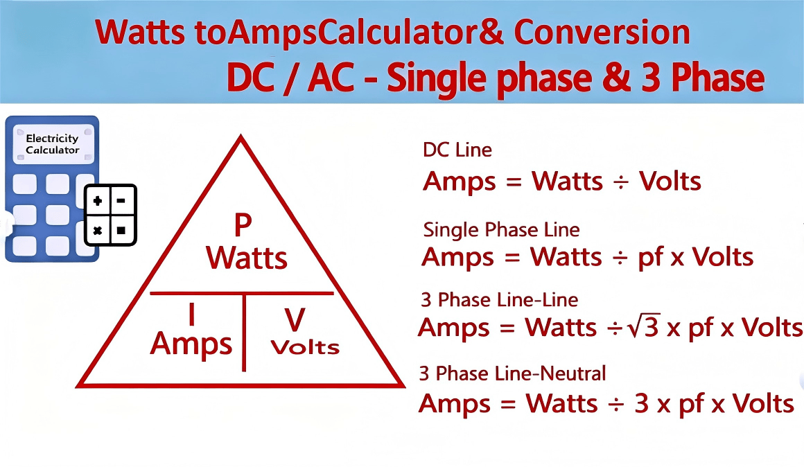
Learn exactly how to convert watts to amps in DC, single-phase AC, and three-phase systems with clea