5 Powerful Insights into HDMI RF Modulators: How to Choose the Perfect Modulator for Coax Distribution
Curious about the HDMI RF Modulator? Learn how HDMI RF modulators convert HDMI signals into RF for c

LEDs are among the most common components in modern electronic products, from indicator lights and display backlights to automotive instrument clusters, medical equipment, industrial control systems, and consumer electronics.
However, an LED is not simply a component that can be placed in either direction.
Because an LED is a polarized semiconductor device, its orientation on a PCB directly affects whether the circuit operates correctly. A reversed LED may fail to illuminate, behave unexpectedly, or, depending on the circuit design, contribute to electrical overstress.
For hardware engineers and procurement teams, the important question is therefore not only what is LED, but also:
How can LED polarity and placement orientation be controlled consistently from PCB design through mass production?
This guide explains the key principles of LED polarity, practical identification methods, SMT placement controls, inspection requirements, and the evidence you can request from a PCB assembly partner.
Understanding what is LED orientation involves recognizing that a light-emitting diode is a polarized semiconductor device with an anode and cathode. Correct LED polarity requires the component’s positive and negative terminals to match the corresponding PCB connections. Proper identification of LED positive and negative terminals helps prevent reverse-bias conditions, non-functional indicators, and assembly defects.
For production, polarity verification should be controlled through PCB markings, component data, placement programming, inspection, and traceability rather than relying on operator interpretation alone.
1. Correct LED polarity is essential.
The relationship between the LED diode anode and cathode must match the circuit design and PCB footprint. Incorrect orientation can result in a non-functional LED and, depending on the circuit, potential electrical stress.
2. Clear PCB design reduces manufacturing ambiguity.
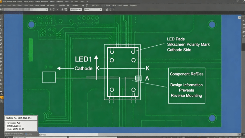
Consistent silkscreen markings, polarity indicators, component references, and correctly defined footprints make LED placement easier to verify during SMT assembly.
3. Inspection and traceability should support the placement process.
AOI, process controls, and production traceability provide multiple opportunities to detect and investigate polarity-related defects before products reach the customer.
When evaluating a PCB assembly supplier, price and placement speed are only part of the equation. For LED-intensive boards, especially LED arrays and products requiring consistent visual performance, the manufacturer’s engineering and inspection processes can have a significant impact on production risk.
| Evaluation Metric | Standard Low-Cost Supplier | Precision-Oriented PCBA Manufacturer |
|---|---|---|
| Engineering Review | Basic file review | DFM and manufacturability review before production |
| SMT Placement Precision | Placement based mainly on programmed coordinates | Controlled programming, component orientation verification and process checks |
| Inspection Protocols | Limited inspection depending on project | SPI/AOI and additional testing according to product requirements |
| Traceability | Basic production records | Lot/batch and process records supporting investigation and traceability |
| Revision Control | May rely heavily on customer file names | Controlled use of applicable drawing, method and revision information |
| Production Transition | Prototype and mass production may be handled differently | Focus on process consistency when moving from sample to volume production |
For procurement teams, the key question is not simply “Can this supplier place LEDs?”
A better question is:
“What controls prevent an orientation error from becoming a repeated production defect?”
A reliable LED assembly process begins before the first PCB enters the SMT line.
At HCJMPCBA, production control can be structured around five critical stages. The exact inspection and testing requirements should be defined according to the customer’s PCB design, BOM, drawings, specifications, and production requirements.
Before production, the manufacturing team reviews the available production data, including PCB files, BOM, component specifications, assembly drawings, and relevant manufacturing instructions.
For LED components, particular attention should be given to:
Where a controlled manufacturing method or inspection instruction is applicable, the method number and revision should be recorded in the production documentation.
This matters because an LED polarity error can be repeated across an entire production lot if an outdated revision is accidentally used.
Engineering review is therefore not merely a documentation exercise. It is an opportunity to identify manufacturing ambiguity before it becomes a production problem.
LEDs can look extremely similar while having different polarity markings, package structures, optical characteristics, and electrical specifications.
Before volume production, the component information should therefore be checked against the approved BOM and manufacturer’s datasheet.
Depending on the project, a pre-production sample plan may define:
For customized LED boards, a controlled sample build can provide an additional opportunity to verify component orientation and functional behavior before committing to larger production quantities.
This is particularly useful when the PCB contains hundreds or thousands of LEDs.
During SMT production, the pick-and-place machine uses programmed component coordinates and orientation information to position components on the PCB.
For surface mount LED polarity, the machine program must correctly correspond with:
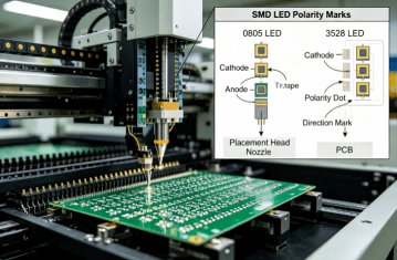
Common SMD LED packages may use different physical indicators to identify the cathode. Depending on the component manufacturer and package, these indicators may include a line, mark, notch, or other package-specific feature.
Therefore, engineers should always verify the actual component datasheet rather than assuming that one physical marking convention applies to every SMD LED.
This is an important point for both engineers and procurement teams.
A supplier should not rely solely on the appearance of the LED package. Component data, machine programming, PCB design information, and inspection results should work together.
After component placement and reflow soldering, AOI can be used to inspect the assembled PCB for visible assembly conditions, including component presence, position, orientation, and solder-related defects within the inspection system’s capabilities.
For LED assemblies, AOI provides an important additional checkpoint for polarity and placement verification.
The reflow process is also important.
An inappropriate thermal profile can affect solder joint formation and, depending on the component and process conditions, may introduce unnecessary thermal stress.
Reflow parameters should therefore be established according to the solder paste, PCB construction, component requirements, and applicable process specifications rather than using one fixed profile for every product.
For complex LED boards, the objective is not simply to achieve a soldered connection. It is to establish a repeatable process window that supports consistent assembly quality.
Visual inspection alone cannot confirm every electrical characteristic.
Where functional testing is specified, the assembled board can be powered and tested under defined conditions to verify whether the LEDs operate as intended.
Depending on the product, test parameters may include:
The test conditions should be clearly defined.
For example, a meaningful electrical record should identify the applicable test method, input conditions, measurement equipment or system, acceptance criteria, and measured result where required by the project.
For production traceability, relevant records can be associated with a lot, batch, serial number, or production date/code, depending on the customer’s traceability requirements.
The goal is to make it possible to answer a practical question:
If a problem is discovered later, can we determine what was produced, under which revision, using which material lot, and through which inspection process?
Partial Screenshot Of Pcb Layout Eda
A professional PCBA supplier should define inspection and testing according to the product’s actual requirements rather than applying the same checklist to every PCB.
The following matrix can be used as a starting point when discussing LED assembly quality requirements:
| Test Parameter | Standard / Specification | Acceptance Criteria | Provided Evidence |
|---|---|---|---|
| LED Polarity Alignment | Approved PCB design, BOM and assembly documentation | Correct orientation according to approved design | AOI/inspection record |
| Solder Joint Fillet Integrity | Applicable assembly workmanship requirements, such as IPC-A-610 where specified | Meets the agreed workmanship criteria | AOI and/or visual inspection record |
| Forward Voltage (Vf) Check | LED manufacturer’s datasheet or customer specification | Within specified electrical range under defined test conditions | Electrical test data |
| Thermal Reflow Process | Approved solder paste/component process requirements | Profile remains within defined process window | Reflow profile record, where required |
| LED Functional Operation | Customer-approved functional test procedure | LED operates correctly under defined conditions | FCT/test record |
The important point is that “tested” should always have a defined meaning.
A test result becomes much more useful when the test condition and acceptance criteria are documented.
If you are purchasing PCB assembly with LED components, the following wording can be adapted for your PO or quality agreement:
LED Assembly Quality Requirement:
LED component polarity and placement shall conform to the approved BOM, PCB design and assembly documentation.
The supplier shall maintain applicable lot/batch traceability and perform agreed inspection and functional testing requirements.
Inspection and test records shall be retained and made available according to the agreed quality documentation requirements.
This wording is intentionally focused on process control and objective evidence rather than imposing undefined or unlimited quality obligations.
For specific projects, the applicable IPC requirements, customer specifications, sampling plans, and test conditions should be agreed before production.
For through-hole LEDs, lead length can sometimes indicate polarity. However, leads may be trimmed, bent, processed, or handled differently during manufacturing.
Therefore, lead length should not be treated as the only source of polarity information.
The component datasheet and physical polarity marking should be used for confirmation.
SMD LEDs can have different package markings depending on the manufacturer and package.
Never assume that a particular line, dot, notch, or package edge always represents the same terminal.
Verify the component datasheet against the approved footprint and assembly orientation.
An ECO can change a PCB footprint, component, polarity marking, or LED arrangement.
If production uses an outdated revision, even a perfectly programmed SMT machine can produce the wrong result.
Revision control should therefore cover the PCB design, BOM, assembly drawing, manufacturing instructions, and relevant inspection information.
Sampling can be appropriate for certain process controls, but it should not automatically replace 100% inspection where the product risk or customer specification requires it.
For LED arrays or applications where every LED position matters, discuss whether 100% AOI and functional verification are appropriate for the project.
For SMD components, the tape-and-reel orientation is part of the manufacturing setup.
An unexpected component orientation can create programming or setup errors if the reel orientation is not correctly verified against the approved production data.
High Speed Smt Mounter Led
LED polarity and placement become particularly important when a PCB contains a large number of LEDs or when the visual and functional performance of each LED position matters.
Typical applications include:
Automotive instrument clusters
A reversed or incorrectly positioned LED can affect indicator functions, display patterns, or visual uniformity.
Display and backlighting systems
LED orientation, placement accuracy, and optical consistency can influence illumination performance.
Industrial indicator arrays
Industrial control panels may use multiple LEDs to communicate machine status. Incorrect placement can result in misleading status indications.
Medical and diagnostic equipment
Indicator LEDs can form part of a user interface or equipment status system. Manufacturing consistency and traceability are particularly important in applications with defined quality requirements.
Smart devices and consumer electronics
Compact PCB layouts often leave limited space between components, increasing the importance of accurate placement and reliable inspection.
For these applications, the cost of an assembly mistake is not necessarily limited to replacing one LED. A production error repeated across a complete lot can create rework, schedule delays, additional inspection, and potentially field-quality concerns.
What is the easiest way to determine LED positive and negative terminals on a through-hole diode?
For a through-hole LED, the datasheet is the most reliable reference. Physical features such as lead length, package shape, or a flattened edge can provide clues, but these should be confirmed against the manufacturer’s documentation, especially after leads have been trimmed or formed.
How do you verify surface mount LED polarity during pick-and-place programming?
The placement program should be checked against the approved PCB footprint, BOM, component datasheet, and assembly orientation. A controlled sample or first-article verification can provide an additional opportunity to confirm orientation before volume production.
What test conditions are applied during LED functional testing?
Test conditions depend on the LED and product requirements. They may include supply voltage, forward current, operating sequence, measurement duration, forward voltage, or optical requirements. The applicable test procedure should define the conditions and acceptance criteria before production testing.
How does a PCBA manufacturer support component traceability?
Traceability can be established through production records connecting relevant material lots or batches with production orders, PCB assemblies, inspection records, and test results. The exact level of traceability should be agreed according to the product and customer requirements.
Why is a pre-production sample plan important for custom LED boards?
A controlled sample build provides an opportunity to verify component orientation, footprint interpretation, placement programming, soldering, and functional behavior before larger quantities are produced. This can reduce the risk of repeating an avoidable setup or engineering error across a full production lot.
What IPC standard is relevant to electronic assembly inspection?
IPC-A-610 is widely used as a workmanship acceptance standard for electronic assemblies. However, the applicable revision, class, customer specification, and acceptance criteria should be agreed for the specific project rather than assuming one requirement applies universally.
Can an LED be damaged if installed backward?
It depends on the circuit and the LED’s electrical characteristics. A reversed LED may simply fail to emit light when reverse-biased within an acceptable range, while excessive reverse voltage can damage certain LEDs. The component datasheet and circuit design should be used to determine the allowable conditions.
Automation reduces dependence on manual placement, but it does not eliminate the possibility of incorrect production data, component orientation setup, footprint errors, or revision-control problems. Effective manufacturing control therefore combines engineering review, programming verification, inspection, and traceability.
When evaluating a PCB assembly supplier, customers do not necessarily need an enormous amount of paperwork.
What matters is whether the available evidence corresponds to the actual production risk.
Depending on the project requirements, customers can discuss requesting:
This evidence-based approach is more useful than simply asking whether a supplier “guarantees quality.”
A capable PCBA partner should be able to explain what is controlled, how it is checked, what the acceptance criteria are, and what records exist when a production issue needs to be investigated.
LED placement may appear to be a straightforward SMT operation, but reliable LED assembly requires control across the entire manufacturing chain—from engineering review and component orientation to SMT programming, soldering, inspection, functional verification, and traceability.
For OEMs and hardware teams, the objective is not simply to place components quickly.
It is to establish a repeatable manufacturing process that minimizes preventable polarity, placement, soldering, and traceability risks as production volume increases.
HCJMPCBA supports PCB assembly projects with engineering review, SMT assembly, 3D SPI, AOI, ICT and other inspection/testing processes according to project requirements.
If you are developing an LED board, indicator panel, display module, industrial controller, medical electronic assembly, or another product requiring controlled PCB assembly, send us your Gerber files, BOM, assembly drawings, and production requirements for an engineering review.
Guangzhou Huachuang Precision Technology Co., Ltd. (HCJMPCBA)
Email: qa@hcjm-pcba.com.cn
WhatsApp: +86 13660883282
WeChat: hcjm-pcba
This article should be reviewed and updated when:
Last reviewed: September 2026
Curious about the HDMI RF Modulator? Learn how HDMI RF modulators convert HDMI signals into RF for c

A pcb board—also known as a printed circuit board—forms the backbone of modern electronics, link
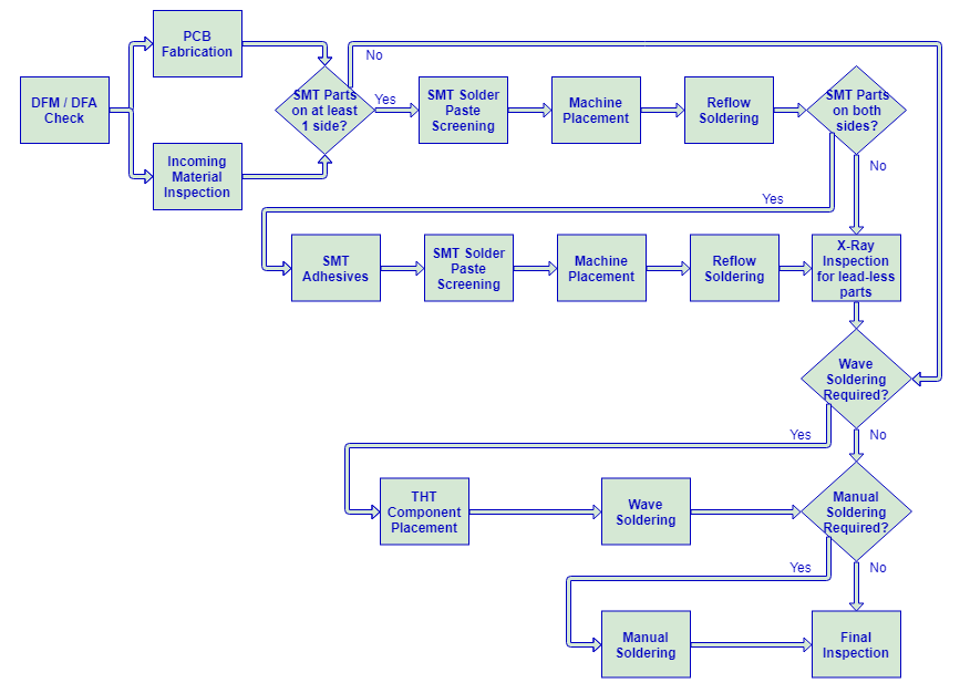
Explore the comprehensive guide to industrial pcb production and the professional pcb manufacturing