Guangzhou Huachuang Precision Technology Co., Ltd.: A Journey of Excellence in Electronics Manufacturing
Since its establishment in 2010,Guangzhou Huachuang Precision Technology Co.,Ltd.has focused on the
PCB functional testing is the process of powering a printed circuit board and verifying that it performs its intended electronic function under real operating conditions. Unlike basic pcb testing methods such as continuity checks or flying probe inspection, functional testing validates firmware behavior, signal processing, and system responses to ensure the board works exactly as designed in the final product.
A pcb functional test (often called a func test) is the final stage of **pcb manufacturing testing** where a powered printed circuit board is evaluated to confirm that it performs its intended electronic function.
During functional testing, engineers simulate real operating conditions such as power input, sensor signals, communication interfaces, and firmware logic. The goal is to verify that the pc board behaves exactly as required in the final device.
This guide is maintained by the HCJMPCBA engineering team and updated with production checklists to ensure every **pcba tester** procedure follows IPC-TM-650 and IPC-A-610 standards for high-reliability electronics manufacturing.
Basic pcb testing methods such as continuity checks or ict tests identify manufacturing faults. However, only pcb functional testing confirms that the pc board actually performs its intended electronic logic when powered.
A properly designed functional test fixture dramatically improves testing throughput in pcb manufacturing testing environments. Without reliable fixtures, even advanced pcb testing equipment cannot guarantee repeatable results.
Professional pcb testing services should always produce raw data logs tied to lot / batch / serial numbers. This ensures accountability and traceability for regulated industries such as medical devices or automotive electronics.
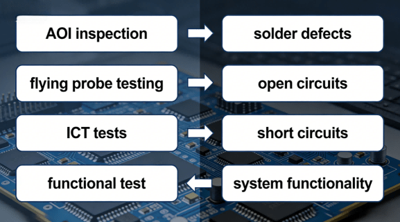
Modern electronics manufacturing uses a layered testing strategy. Each pcb testing method detects different defect categories.
Testing hierarchy typically follows this order:
1. Visual inspection and AOI
2. Flying probe electrical testing
3. In-circuit testing (ICT)
4. Functional test verification
5. System level validation
This layered approach ensures that assembly defects, electrical connectivity problems, and system-level logic failures are all detected before shipment.
To understand pcb functional testing, it is important to first define what is pcb validation in an industrial context.
A printed circuit board is the core electrical platform that connects electronic components through conductive copper traces. During production, manufacturers must verify that the pc board performs correctly before shipment.
This verification process is known as pcb board testing.
Typical printed circuit board testing methods include:
visual inspection
automated optical inspection (AOI)
flying probe test
ICT tests (in-circuit testing)
functional test in manufacturing
Each method detects different types of defects during the pcb testing process.
For example:
| Testing Method | What It Detects |
|---|---|
| AOI | Solder defects |
| Flying probe | electrical connectivity |
| ICT | component placement errors |
| Functional test | full system behavior |
Modern pcb manufacturing testing combines these techniques to ensure reliable electronics production.
Hcjmpcba Pcb Function Testing Methods Overview
A common engineering question is how to choose between flying probe, ict tests, and functional test fixtures.
These pcb testing equipment types serve different purposes in the pcb testing process.
A flying probe test uses movable probes controlled by automated machines to electrically test pads on a pc board.
Advantages:
no fixture required
flexible for prototype runs
ideal for NPI production
Disadvantages:
slower testing speed
not suitable for high-volume production
ICT tests use a bed-of-nails fixture to probe hundreds of test points simultaneously.
Advantages:
extremely fast testing
high fault coverage
Disadvantages:
expensive fixture cost
design must include sufficient test points
A pcb functional test powers the printed circuit board and simulates real-world operating conditions.
Advantages:
verifies actual circuit functionality
detects firmware or logic errors
validates system performance
Because of these advantages, functional test in manufacturing is considered the final verification stage before shipment.
| Testing Method | Primary Purpose | Production Stage | Coverage Type | Best Use Case |
|---|---|---|---|---|
| Flying Probe | electrical connectivity verification | prototype / NPI | open / short detection | low volume |
| ICT Test | component level validation | mass production | component placement | high volume |
| Functional Test | system behavior validation | final production stage | firmware + hardware | finished product |
Professional factories combine all three printed circuit board testing methods to ensure complete defect coverage.
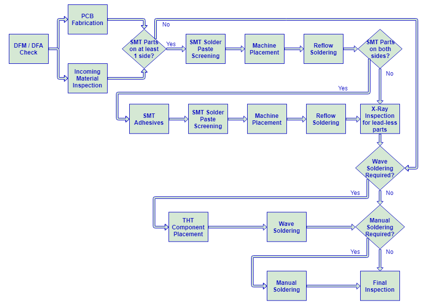
In modern electronics manufacturing, functional testing is widely considered the final verification step before shipment because it validates real product behavior rather than only manufacturing defects.Testing a pc board in industrial production follows a standardized workflow.
Engineers integrate test points during PCB layout.
DFT ensures the printed circuit board tester can access critical signals such as:
power rails
ground reference
communication interfaces
analog measurement points
Without DFT, automated pcb testing equipment cannot effectively evaluate the board.
A functional test fixture holds the PCB and connects it to a pcba tester.
Typical components include:
spring test probes
mechanical clamps
power supply interfaces
communication ports
These fixtures ensure stable electrical contact during board functional test procedures.
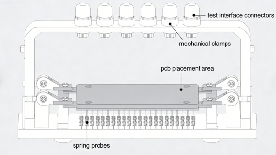
Hcjmpcba Pcb Functional Test Fixture
The pcba tester communicates with the board through interfaces such as:
UART
I2C
SPI
CAN
Test scripts validate system responses and compare them with predefined parameters.
Professional pcb functional testing must operate under defined test conditions.
Typical parameters include:
| Condition | Standard |
|---|---|
| Temperature | 25°C |
| Humidity | 45–55% |
| Power supply tolerance | ±5% |
These conditions follow IPC-TM-650 testing standards.
At HCJMPCBA, pcb testing services follow a structured engineering framework designed to reduce production risk.
Every pcb functional test is documented with a unique Method Number.
This document defines:
test procedures
equipment configuration
firmware version
acceptance criteria
When a product design changes, the Revision code ensures the correct procedure is used during testing.
Mass production follows statistical sampling plans based on ISO 2859.
However, for critical electronics, HCJMPCBA can perform:
100% functional testing
additional stress testing
Traceability is increasingly required in regulated industries such as medical electronics, automotive control systems, and industrial automation. Maintaining complete testing records allows manufacturers to perform root cause analysis and regulatory audits when necessary.Each printed circuit board receives a unique identifier linked to:
manufacturing batch
testing equipment ID
operator logs
raw test data
This traceability system enables root cause analysis if field failures occur.
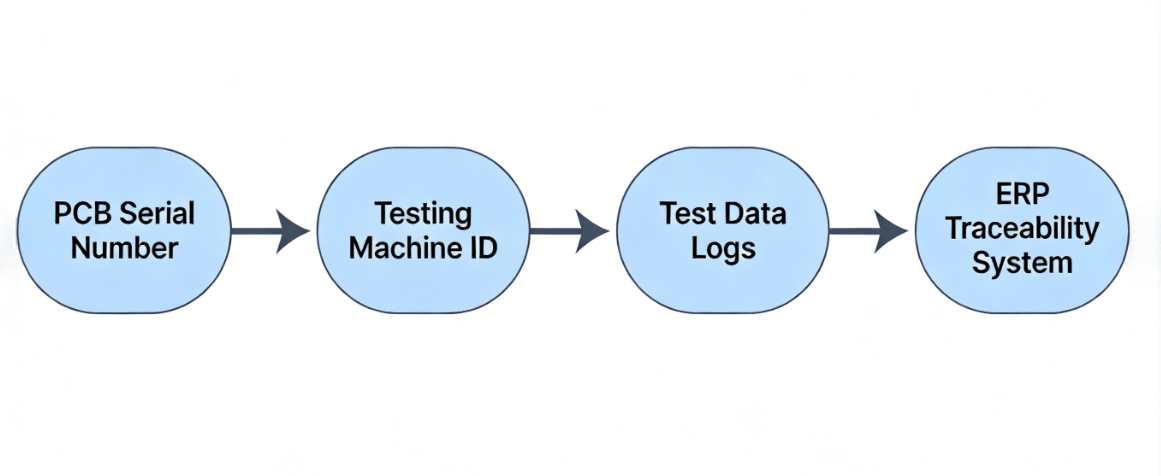
Hcjmpcba Pcb Testing Traceability System
| Document | Purpose | Evidence |
|---|---|---|
| Functional test report | verify performance | raw data logs |
| Calibration certificate | ensure tester accuracy | equipment certification |
| Sample plan document | verify testing coverage | AQL records |
| Traceability report | track production history | lot / batch / serial |
Procurement managers may include the following clause in purchase agreements:
“The supplier shall perform pcb functional testing according to IPC-TM-650 standards. All pcb manufacturing testing must follow documented Method Number + Revision procedures. The supplier shall maintain raw data records and provide full traceability (lot/batch/serial) for every shipment.”
Insufficient test points limit the effectiveness of pcb tests.
Many electronics require specific startup timing.
Unstable functional test fixtures lead to inconsistent measurements.
A pcb functional test must verify firmware behavior as well as hardware.
Without raw test data, troubleshooting field failures becomes nearly impossible.
Consider an HVAC controller board used in industrial equipment.
A typical pcb testing process would include:
1.flying probe verification
2.ICT component validation
3.full pcb functional test
During functional testing:
sensors are simulated
relay outputs are activated
communication interfaces are verified
This ensures the printed circuit board performs correctly before shipment.
Q:How to test pcb board without expensive fixtures?
A:For prototypes, flying probe testing is often the most cost-effective solution.
Q:What is the difference between flying probe vs ict?
A:Flying probe requires no fixture but is slower.
ICT tests require fixtures but allow faster mass testing.
Q:Why is pcb functional testing important?
A:Because it confirms that the pc board performs its real electronic function.
Q:What equipment is used for pcb testing?
A:Typical pcb testing equipment includes flying probe testers, ICT systems, and functional test fixtures.
Q:What standards govern pcb testing?
A:Common standards include:
IPC-A-610
IEC 61189
Q:What is the difference between PCB testing and PCB functional testing?
A:PCB testing refers to all inspection and electrical verification methods used during manufacturing, including flying probe and ICT tests.
PCB functional testing specifically evaluates whether the finished board performs
When sourcing pcb testing services, professional suppliers should provide:
functional test logs
equipment calibration certificates
traceability documentation
raw electrical test data
These documents ensure transparency in pcb manufacturing testing.
In high-reliability electronics manufacturing, the combination of flying probe inspection, ICT validation, and final functional testing provides the most complete defect detection strategy.
At HCJMPCBA, these testing layers are integrated with documented test procedures, equipment calibration logs, and traceable raw data records to ensure every PCB assembly meets strict industrial quality standards.
PCB functional testing ensures that a printed circuit board performs its real operating function before shipment.
Unlike earlier pcb testing methods that detect manufacturing defects, functional testing verifies firmware behavior, signal processing, and system responses under real operating conditions.
For complex electronics products, combining flying probe testing, ICT validation, and board functional testing provides the most reliable quality assurance strategy.
Reliable electronics manufacturing requires rigorous pcb functional testing and transparent production data.
Update triggers: standard revision changes / recurring questions / production checklist updates.
Since its establishment in 2010,Guangzhou Huachuang Precision Technology Co.,Ltd.has focused on the
This article analyzes the future trends of the electronic manufacturing industry, including technolo
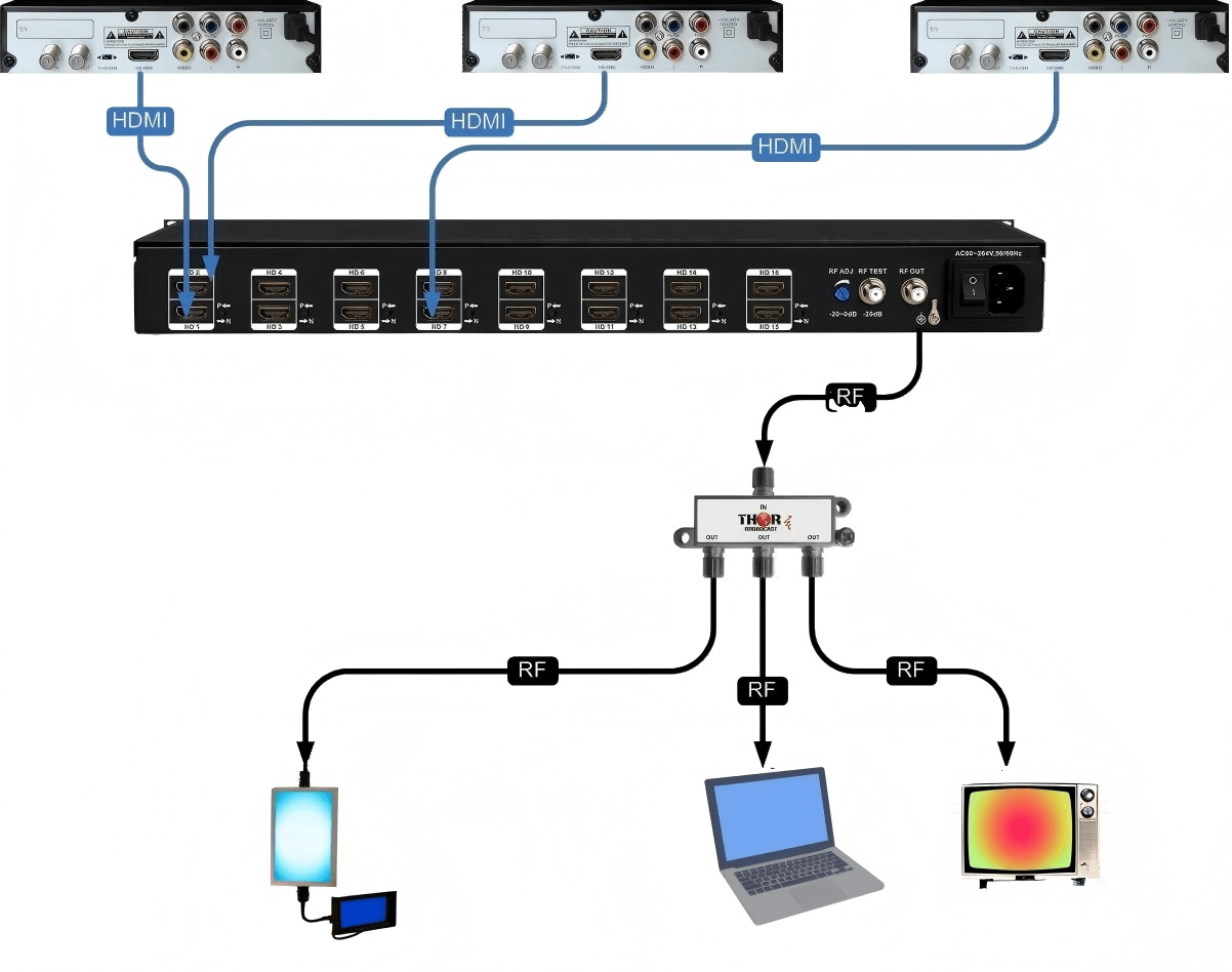
Curious about the HDMI RF Modulator? Learn how HDMI RF modulators convert HDMI signals into RF for c