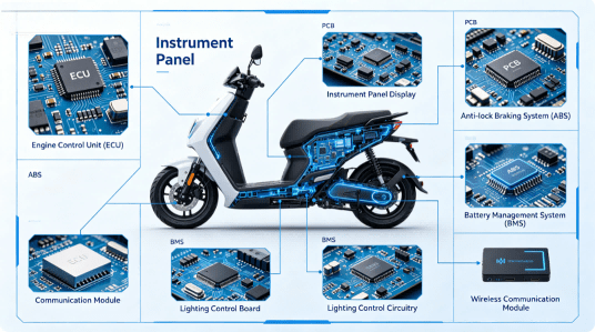
7 Critical Types of Circuit Board Found in Motorcycles: A Complete Guide to Motorcycle Electronics and Reliable PCBA Manufacturing
Direct Answer Modern motorcycles contain multiple circuit board systems rather than a single PCB. Co

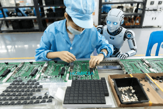
Hcjmpcba Robot Pcb
A high-performance Robotics PCBA must prioritize structural integrity, thermal resilience, and signal precision. Unlike standard boards, a robot circuit board operates under constant vibration and varying thermal loads. This guide is maintained by the HCJMPCBA engineering team and updated with production checklists to ensure global compliance with IPC-A-610 Class 3 standards.
A robot circuit board is not just another PCB. It often controls motion, sensing, communications, power stages, and safety logic simultaneously. Unlike low-duty consumer devices, robots may run continuously in factories, warehouses, laboratories, farms, or public environments.
Typical robotics use cases include:
That means the pcb robot architecture must tolerate real-world stress, not just pass a bench test.
Robots move. They stop suddenly. They vibrate. They may collide, carry loads, or travel over uneven surfaces.
A robotics PCBA should therefore consider:
Repeated micro-vibration can crack solder joints over time. This is especially relevant for wheel-drive robots, robotic arms, and mobile platforms.
What to ask a supplier:
Do they review connector anchoring, board flex risk, and component retention before production?
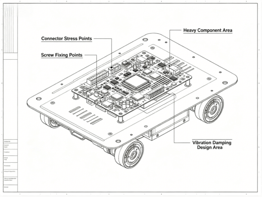
Structural Diagram Of The Robot Control Board Mounted On The Metal Chassis Hcjmpcba
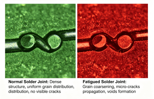
Micrograph Of Solder Joint Fatigue Cracks
Modern circuit robotics systems often integrate:
Poor layout or weak assembly quality can create unstable behavior that appears “random” in the field.
Key design and manufacturing controls include:
For a circuit board robot, stable signals matter as much as code quality.
Many robots combine logic boards with motors, battery systems, charging circuits, or LED loads. Heat is often underestimated.
A strong robotics board should evaluate:
Ignoring thermal behavior is a common cause of resets, reduced battery life, and premature failure.
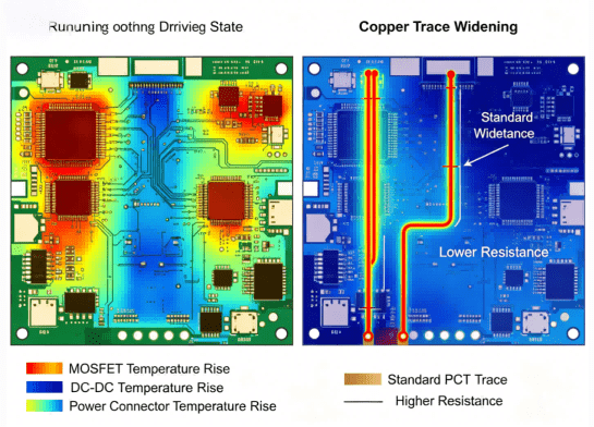
Thermal Imaging Diagram Of Robot Circuit Board Hcjmpcba
Many field failures come from connectors, terminals, or manually stressed joints.
This is where robotic soldering, automated soldering, or selective process control becomes valuable. Repetitive high-stress joints often benefit from repeatable solder volume, dwell time, and temperature control.
Examples:
A reliable factory should know when SMT reflow is enough and when robotic soldering or secondary reinforcement is justified.
Motors, relays, switching regulators, and wireless modules can coexist on one board. Without noise control, robots may:
Mitigation methods include:
Robotics programs often stay in service for years. Replacement boards must match prior revisions.
Important lifecycle practices:
A supplier focused only on shipment date may ignore long-term service cost.
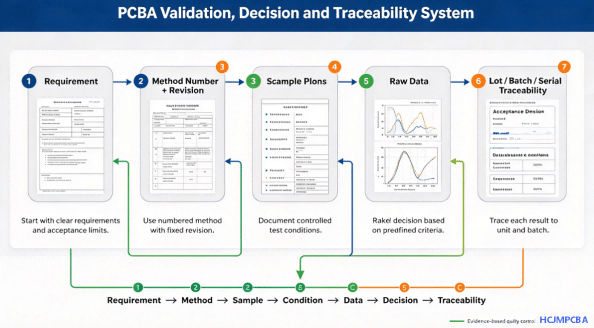
When 5,000 units are in the field, the question is not “Did we build them?” but “Which exact batch used that component lot under which process revision?”
Strong traceability should include:
This reduces containment time if a supplier issue appears later.
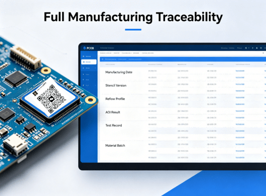
Hcjmpcba Pcb Robot Full Manufacturing Traceability
| Criteria | Advanced Manufacturing Partner | Standard Assembler | Lowest-Cost Shop |
|---|---|---|---|
| DFM Review | Structured | Basic | Minimal |
| Automated PCB Assembly | Yes | Partial | Variable |
| Test Evidence | Raw data available | Pass/fail only | Limited |
| Traceability | Lot/Batch/Serial | Batch only | Weak |
| Engineering Support | Strong | Moderate | Low |
| Lifecycle Change Control | Formal | Informal | Reactive |
| Best Use Case | Robotics / Industrial | General products | Price-only buys |
| Claim | Evidence to Request | Why It Matters |
|---|---|---|
| IPC workmanship capability | Training records / internal criteria aligned to IPC-A-610 & J-STD-001 | Consistent quality language |
| Solder process control | Reflow profile / soldering WI / parameter logs | Repeatability |
| X-Ray capability | Sample images / defect library | Hidden joints |
| Functional test capability | Test fixture summary / coverage list | Real performance |
| Traceability | Sample serial report | Fast containment |
| Material control | Incoming inspection records | Component risk reduction |
Each controlled operation should be linked to a documented method number and revision status. Examples:
Why this matters: operators follow the current standard, not memory.
Before mass release, validation should define:
Sampling may align with customer requirements or recognized AQL frameworks depending on project risk.
A serious robotics build should not stop at visual inspection.
Possible controls:
Test conditions should state voltage, load, temperature, firmware version, pass criteria, and fixture revision.
Pass/fail is useful. Raw data is better.
Examples:
Raw data supports engineering decisions later.
HCJMPCBA supports production-oriented traceability practices for lot/batch/serial management, enabling faster root-cause isolation and controlled corrective action during mass production programs.
At HCJMPCBA, we don’t just assemble; we engineer reliability. Our robotics manufacturing process follows a strict Method Number + Revision system to ensure consistency across batches.
Robotics applications often involve high-stress environments. Standard manual soldering cannot guarantee the repeatability required for a circuit robotics system. We utilize automated soldering machines and robotic soldering stations to ensure every joint meets the wetting requirements of J-STD-001. Using a solder robot eliminates the human error factor in high-density robot solder points.
Trust is built on data. For every automated pcb assembly project, we provide:
Sample Plan: Based on AQL 0.65/1.0 or client-specific requirements.
Test Conditions: Including AOI, 3D X-Ray for BGA integrity, and In-Circuit Testing (ICT).
Raw Data Access: Clients can request the original testing logs to verify the performance of their automated circuit board assembly.
| Feature | Standard Workshop | HCJMPCBA (Premium) |
| Soldering Tech | Manual/Standard Wave | Automated Soldering / Robotic Solder |
| Traceability | None or Batch only | Full Lot/Batch/Serial Traceability |
| Standard | IPC Class 1 | IPC-A-610 Class 2/3 |
| Design Review | Basic Check | Deep DFM & SI/PI Analysis |
| Artifact | Purpose | Evidence for Client |
| Method Revision | Consistency | Process Control Document (PCD) |
| X-Ray Logs | Internal Integrity | 3D Imagery of BGA/QFN Joints |
| IQC Reports | Component Quality | Verified traceability (lot/batch) of ICs |
Step 1: Define the Real Operating Environment
State vibration, duty cycle, temperature range, ingress risk, and expected service life.
Step 2: Submit Complete Engineering Data
Provide:
Step 3: Run DFM Review Before PO Release
Check footprints, panelization, polarity risk, connector access, thermal bottlenecks, and sourcing constraints.
Step 4: Validate with Pilot Build
Build a controlled sample lot before full production.
Step 5: Approve Test Conditions and Reports
Define what data must be reported, not only “PASS”.
Step 6: Launch Controlled Mass Production
Freeze revision status, labeling logic, and change approval workflow.
Supplier shall manufacture Robotics PCBA to approved revision-controlled files only.
Supplier shall maintain lot/batch/serial traceability for materials and finished assemblies.
Supplier shall provide agreed test records including defined electrical test conditions.
No component substitution is permitted without written approval.
Process changes require documented notification and authorization.
An AMR fleet uses battery-powered control boards in warehouses operating 16 hours per day. Initial prototypes worked, but field returns appeared after three months. Root cause analysis found connector fatigue plus inconsistent replacement components.
With controlled sourcing, reinforced solder strategy, serial traceability, and validated alternates, repeat failures dropped sharply. This is why robotics programs need manufacturing systems, not just assembly capacity.
Q1. What is a Robotics PCBA?
A PCB assembly designed for robotic control, sensing, communication, and power functions under dynamic operating conditions.
Q2. Is robotic soldering better than manual soldering?
For repetitive critical joints, robotic soldering often improves consistency, parameter control, and documentation.
Q3. What is the difference between PCB and PCBA?
PCB is the bare board. PCBA is the assembled board with components installed and tested.
Q4. Why does traceability matter in robot circuit board production?
It shortens containment time, supports recalls, and accelerates root-cause analysis.
Q5. Should every robot board use X-Ray inspection?
Not always. It is most useful for hidden joints such as BGA, QFN voiding concerns, or high-risk assemblies.
Q6. What files should buyers send first?
Gerber, BOM, assembly notes, test needs, annual volume, and target application.
Q7. Can automated soldering machines reduce defects?
Yes—when correctly programmed and validated, automated soldering machines improve repeatability on suitable joints.
Q8. How should buyers compare suppliers?
Compare engineering depth, process control, evidence quality, responsiveness, and long-term support—not only price.
Q9: Why is automated soldering critical for a robot circuit board?
A: Robots involve moving parts. Automated soldering ensures uniform solder fillets that withstand mechanical fatigue far better than manual joints.
Q10: What standards does HCJMPCBA follow for pcb robotics?
A: We strictly adhere to IPC-A-610G and J-STD-001, often providing Class 3 (Medical/Aerospace grade) reliability for industrial circuit robotics.
Q11: How do you handle component shortages for robotics projects?
A: Our Component Sourcing team provides BOM optimization and suggests verified alternatives to ensure the automated pcb assembly timeline isn’t delayed.
During audit or RFQ review, buyers can request:
A reliable Robotics PCBA partner does more than populate components. It helps prevent failure before production starts, proves process capability with evidence, and protects scale-up with disciplined controls.
For robotics programs, sourcing quality is a design decision.
Update triggers: standard revision changes / recurring questions / production checklist updates.
Direct Answer Modern motorcycles contain multiple circuit board systems rather than a single PCB. Co
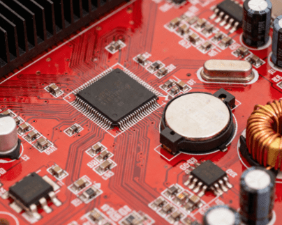
Learn what kind of motherboard do I have using seven proven methods. From Windows built-in tools to
If you want to quickly understand how to use a multimeter, this guide explains the practical steps u