What Is a PCB? A Comprehensive Guide to Printed Circuit Boards
A PCB (Printed Circuit Board) is the foundation of modern electronics, providing mechanical support
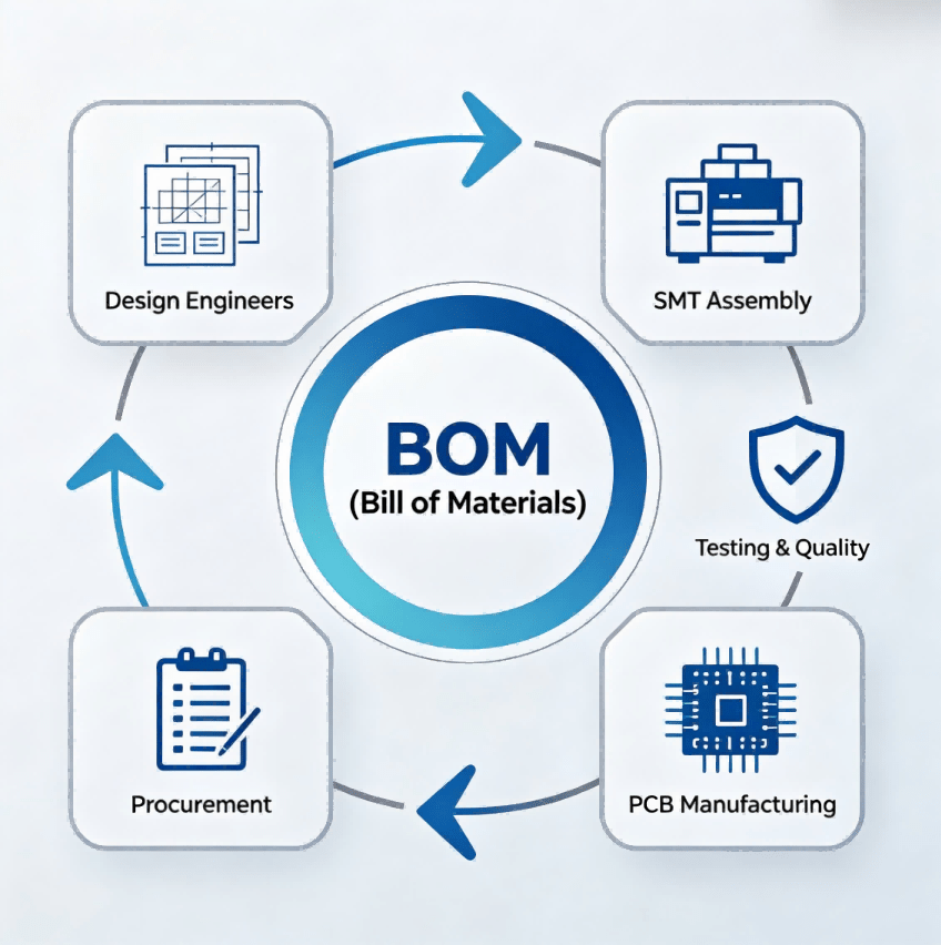
A protoboard (or prototype board) is a permanent, solderable circuit board used to transition electronic designs from temporary breadboards to robust, functional prototypes. Unlike breadboards, which use friction-fit terminals, a protoboard requires soldering to establish mechanical and electrical connections, making it suitable for high-vibration environments and long-term testing. This guide is maintained by the HCJMPCBA engineering team and updated with production checklists to ensure a seamless transition from prototype validation to high-volume PCBA manufacturing.
Functional Validation: Protoboards are essential for verifying circuit integrity in real-world conditions where breadboards lack reliability.
Solder Integrity: Proper soldering techniques, aligned with IPC standards, determine the debugging efficiency and signal stability of the proto pcb.
Production Readiness: Transitioning from a protoboard to a professional PCB requires a shift toward DFM (Design for Manufacturing) and strict traceability (lot/batch/serial) protocols.
A protoboard, often referred to as a perfboard or prototype board, is a pre-drilled material (typically FR4 or SRBP) covered with individual copper pads around each hole. In the engineering workflow, it serves as the middle ground between a temporary proto breadboard and a custom-manufactured PCB.
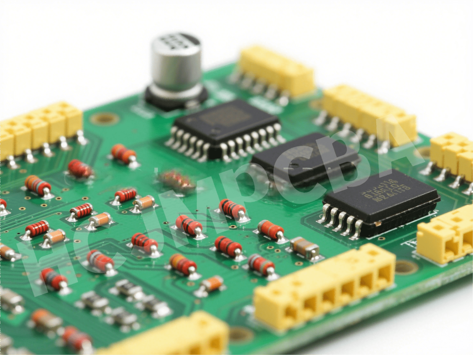
Most high-quality proto pcb boards utilize FR4 substrate—the same glass-reinforced epoxy used in industrial PCBA. The holes are typically spaced at a standard 0.1-inch (2.54mm) pitch to accommodate integrated circuits (ICs), transistors, and headers. Unlike a rotoboard or stripboard, where pads are connected in long rows, a standard perfboard has isolated pads, requiring the engineer to create connections using jumper wires or solder bridges.
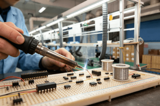
Hcjmpcba Engineers Solder Components On The Protoboard
For many developers, the question of protoboard vs breadboard depends on the project stage. While a proto breadboard is unmatched for rapid component swapping, it suffers from parasitic capacitance and loose connections.
| Feature | Protoboard | Breadboard |
| Soldering | Required | Not required |
| Reliability | High (Permanent) | Low (Temporary) |
| Signal Stability | Excellent | Limited by contact resistance |
| Best Use Case | Functional Testing / Field Use | Initial Concept Validation |
| Transition | Directly to proto pcb | To protoboard or PCB |

Protoboard Vs Breadboard
Engineers utilize proto circuit boards in several professional and hobbyist scenarios:
Guitar Pedal PCB Development: Designers often use a breadboard guitar pedal setup for tone shaping, then move to a breadboard pcb board (protoboard) for road-testing the circuit.
Robotics Prototyping: Validating sensor arrays on a circuit board robot before committing to a multi-layer automated pcb assembly run.
Industrial Debugging: Creating “one-off” interface tools for factory floor diagnostics where a custom pcb manufacturing quote might not be cost-effective for a single unit.
Using a protoboard circuit effectively requires more than just placing components. Follow this professional sequence:
Schematic Finalization: Confirm your circuit on a breadboard before moving to the proto board. Define the signal flow to minimize wire crossings.
Component Placement: Place critical components (ICs, microcontrollers) first. Center them to allow room for routing in all directions.
Power and Ground Rail Planning: Establish dedicated rows for VCC and GND. In high-frequency designs, keep these paths as short as possible.
Jumper Preparation: Use solid-core wire for permanent jumpers. Plan your protoboard online or on paper first to visualize the “nest.”
Soldering (Low to High Profile): Solder smaller components like resistors and diodes first, moving to larger capacitors and headers last.
Inspection and Continuity: Use a multimeter to verify every protobord connection against the schematic.
Documentation: Record the method number + revision of your prototype to ensure you can replicate results during the pcb manufacturing quote phase.
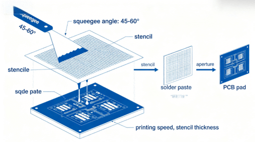
Soldering on a perfboard is distinct from soldering on a professional PCB with a solder mask. Without a mask, solder bridging is a high risk.
Through-Hole Solder Wetting: Ensure the solder flows completely through the hole to create a “fillet” on the copper pad. This is the same standard used in automated soldering.
Avoid Pad Lifting: Excessive heat (over 350°C for too long) will cause the copper pad to delaminate from the FR4.
Bridge Prevention: When creating a protoboard circuit, use small amounts of flux to ensure the solder clings only to the intended pads. For high-reliability prototypes, engineers may simulate the consistency of a soldering robot by using temperature-controlled stations.
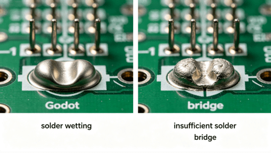
Good Solder Joint Vs Cold Solder Joint
| Verification Item | Typical Requirement | Evidence Category |
| Solder Joint Inspection | Concave fillet, no cold joints | IPC-A-610 Compliance |
| Continuity Test | < 0.5 Ohms per trace | Electrical Validation |
| Mechanical Stability | Components flush to board | Vibration Resistance |
| Traceability | Marked Batch/Date | Traceability (lot/batch/serial) |
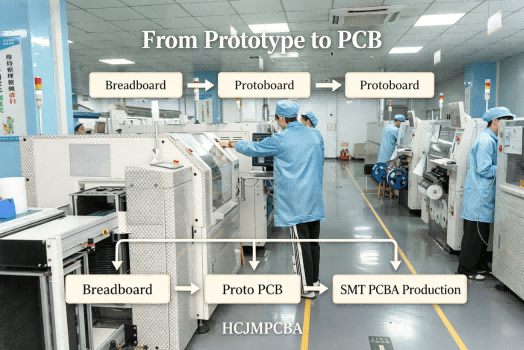
The ultimate goal of using a protoboard is to prove a concept is ready for mass production. When moving from a breadboard pcb board to a professional PCBA workflow, several factors change:
At Guangzhou Huachuang Precision Technology (HCJMPCBA), our engineering teams help customers transition from hand-soldered prototypes to scalable production. While a protoboard is hand-crafted, a professional PCB utilizes automated circuit board assembly and robotic soldering for 100% repeatability.
When requesting a pcb assembly online quote, ensure your design files (Gerbers) are optimized via DFM (Design for Manufacturing) to avoid the “prototype mistakes” common in hand-wired boards.
Overheating Copper Pads: Resulting in lifted pads and broken traces.
Poor Grounding Layout: Creating ground loops that interfere with sensitive analog signals.
Excessive Jumper Crossing: Increasing the risk of short circuits and signal interference.
No Revision Documentation: Losing track of which method number + revision was the “working” version.
Direct Layout Porting: Attempting to use a breadboard layout for a PCB without optimizing for automated pcb assembly.
Consider the development of a guitar pedal pcb. An engineer starts with a breadboard guitar pedal to tweak the distortion circuit. Once satisfied, they move to a protoboard to fit the circuit into a metal enclosure for road testing. After the prototype survives a tour, they submit the files for a pcb manufacturing quote at HCJMPCBA to produce 500 units. This transition ensures that the “soul” of the prototype is preserved in a high-quality, traceable mass-produced product.
“Supplier shall maintain revision-controlled assembly records, soldering inspection criteria per IPC-A-610, and continuity verification data for all prototype PCB builds and small-batch production.”
From Prototype To Pcb
What is a protoboard used for?
It is used for creating permanent, soldered versions of electronic circuits for testing, validation, and low-volume applications.
Protoboard vs breadboard: which is better?
Breadboards are better for quick experiments; protoboards are better for reliability, portability, and long-term signal stability.
Can a protoboard become a final product?
Yes, in DIY or industrial “one-off” cases, but for commercial products, a professional PCBA is required for safety and regulatory compliance (UL/CE).
What solder is best for protoboard assembly?
A high-quality 60/40 Lead-Tin or Lead-Free SAC305 solder with a flux core is recommended for clean protoboar joints.
Is perfboard the same as protoboard?
Yes, perfboard is a specific type of protoboard with individual, non-connected pads.
How do engineers move from protoboard to PCB?
By capturing the final prototype circuit into EDA software (like KiCad or Altium), performing DFM checks, and requesting a pcb manufacturing quote.
Solder Inspection Photos: High-resolution AOI or manual macro photos.
Continuity Test Records: Logs showing all nets were verified.
Revision Tracking: Documentation of method number + revision.
Raw Data: Thermal profiles and test conditions used during assembly.
For more information about PCBA services, please contact Guangzhou Huachuang Precision Technology (HCJMPCBA).
Update triggers: standard revision changes / recurring questions / production checklist updates.
A PCB (Printed Circuit Board) is the foundation of modern electronics, providing mechanical support

Since its establishment in 2010,Guangzhou Huachuang Precision Technology Co.,Ltd.has focused on the
Discover the 7 powerful strategies to evaluate and select the best Automotive PCB Fabrication & Asse